Posts: 4,683
Threads: 93
Joined: Feb 2012
Location: Perth, Australia
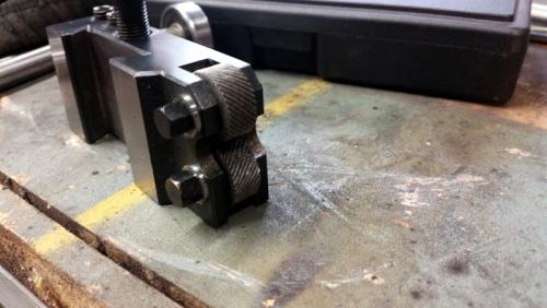
I made some new shoulder bolts for the bump knurler on my mates lathe. The soft Chinese ones had worn out and the result was a smear, rather than a knurl. I picked up some O1 and milled the hex and then turned the rest. Heated them to cherry red and quenched them in some old oil. I then heated them to the point where the oil burned off and let them cool. I had to use washers, as the holes were countersunk for some reason. The thread is M6x1.00 and the hex is 8mm.
After heat treating - compared to the original worn out one

All done!
Hunting American dentists since 2015.
Posts: 691
Threads: 14
Joined: Feb 2015
Location: Oakland, California
A friend scored a very nice after-market muffler for his bike on eBay for cheap because it was missing it's mid-pipe. He consulted with me and I recommended we build one out of stainless. He ordered the parts -- a pre-bend, a straight section and reducer -- and we had a little garage party putting it together.
What was nice about the build was that no parts were scrapped, all the joints fitted very nicely and we were done an hour before we thought we'd be done.
Normally, you start building an exhaust from both ends and it meets in the middle, and that middle joint is usually the one which takes as much time as the whole rest of the pipe and has a terrible fitting joint anyway. This one came together just so and fairly quickly. As our Brit friends say, I was well chuffed.
Posts: 3,003
Threads: 51
Joined: Apr 2012
Location: Ontario
The following 3 users Like f350ca's post:
Pete O (02-08-2016), EdK (02-08-2016), Mayhem (02-09-2016)
Was making bearing mounts for a transfer case on the processor and needed to remove a pile of metal. Started with 4 1/2 dia stock and needed to rough bore it to 2.65 ID. My Kenametal boring bar takes a 322? triangular insert, I've always used the two sided regular inserts in it. It does well with maybe .030 depth of cut. Ran across these inserts, no idea what they are called,(help Ken), .1 depth of cut at 500 rpm and ,007 feed rate was effortless with masses of C shaped chips flying.
![[Image: IMG_2041.jpg]](https://lh3.googleusercontent.com/-Enw9lLhfvDk/Vrke3bwvh4I/AAAAAAAADlI/iwHdDne3UEc/s1280-Ic42/IMG_2041.jpg)
Final rough bore, ready to be welded into the case, then final line bored to size.
![[Image: IMG_2042.jpg]](https://lh3.googleusercontent.com/-2h8fUOPLt_M/Vrke3swn_yI/AAAAAAAADlM/SbY2eaTuBqQ/s1280-Ic42/IMG_2042.jpg)
Free advice is worth exactly what you payed for it.
Greg
Posts: 1,827
Threads: 51
Joined: Apr 2012
Location: Oklahoma
The following 2 users Like dallen's post:
Mayhem (02-09-2016), Highpower (02-09-2016)
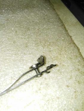
worked on making a screw for a Remington that I'm trying to bring back from the grave
dallen, proud to be a member of MetalworkingFun Forum since Apr 2012.
If life seems normal, your not going fast enough! 
Posts: 2,344
Threads: 53
Joined: Feb 2012
Location: Spencer MA USA
The following 1 user Likes PixMan's post:
Mayhem (02-09-2016)
Greg,
It's kind of hard to tell but I think you may need TNMG33x inserts for that boring bar, not 322. Those would be 3/16" thick instead of 1/8" thick.
While that's a common insert designation, the specific one I see there is special for boring bars as it give a high positive easy-cutting action in a bore and reduces chatter. The chipbreaker shape that Walter Valenite uses is available in left hand (for boring bars) or right hand (for O.D. turning) and they only have the chipbreaker is only on one side, making it a TNMM. You can use either thickness because your top clamp can reach and you can adjust height. If you get me the nomenclature off the bar I can tell for certain what insert should be in there. If, for example, it's a 1" bar the nomenclature might read "S16-MTONR 3". Insert thickness isn't part of that. Thickness is determined by the depth of the pocket and the total height of the carbide anvil and the cutting insert.
If you were shopping eBay or elsewhere for more of that style insert, look for TNMM332 (or 331)-EL-PN1 or EL-PN2. The difference is in just how deep and tight the chipbreaker shape might be. I can't tell which you may have, but either works as that one did and it's pretty cool, eh?
Posts: 3,003
Threads: 51
Joined: Apr 2012
Location: Ontario
Thanks Ken, please remember I'm insert challenged. This insert is in fact thicker than 322?, probably is 3/16 thick. I'll get the nomenclature off the bar for you.
Cool is putting it mildly, that insert just ate the metal, the lathe has 10 hp but you couldn't really hear load at that .1 DOC. And the chip control was probably the best I've ever had.
Free advice is worth exactly what you payed for it.
Greg
Posts: 3,003
Threads: 51
Joined: Apr 2012
Location: Ontario
Hi Ken
Here's a photo of that bar.
![[Image: IMG_2045.jpg]](https://lh3.googleusercontent.com/-_jaQyR1VD1o/VrlzmUzFpYI/AAAAAAAADlk/LU5y4o9SZrQ/s1280-Ic42/IMG_2045.jpg)
Thanks Greg
Free advice is worth exactly what you payed for it.
Greg
Posts: 3,003
Threads: 51
Joined: Apr 2012
Location: Ontario
The following 3 users Like f350ca's post:
Pete O (02-09-2016), Mayhem (02-10-2016), EdK (02-10-2016)
Had some smaller versions of that insert I was using in the boring bar, so made a 3/4 inch bar for the indexing head.
![[Image: IMG_2046.jpg]](https://lh3.googleusercontent.com/-9YZdhsuPjl8/VrqXQatj1PI/AAAAAAAADmE/ZM4hulElkIo/s1280-Ic42/IMG_2046.jpg)
Again it cut amazingly well, especially for the length of the bar. Needed about 7 inches to reach into the gearbox.
![[Image: IMG_2047.jpg]](https://lh3.googleusercontent.com/-I8RfkH7x3eI/VrqXQU6P7NI/AAAAAAAADmE/FGh98MY7VcQ/s1280-Ic42/IMG_2047.jpg)
Free advice is worth exactly what you payed for it.
Greg
Posts: 716
Threads: 32
Joined: Apr 2012
Location: Washington, USA
That's encouraging. One of these days I need to venture into carbide and making a holder is very appealing.
Posts: 4,495
Threads: 187
Joined: Feb 2012
Location: Missouri, USA
The following 2 users Like Highpower's post:
EdK (02-12-2016), f350ca (02-12-2016)
While my mill is apart I wanted to look into something that has been bugging me for a couple of years now. Once in awhile my quill would stick when down feeding using the fine-feed wheel. Most often when I tried to come down a few thousandths to a specific depth. The quill movement would start to get stiff, then suddenly jump down much farther than I wanted to go. The outside of the quill is clean and smooth, as is the bore in the head that it rides in. This happened to me before - years ago, before I had installed my power drawbar. Adding some grease to the splines on the spindle made the problem go away.... temporarily.
With the head apart I was able to get a good look at the spindle splines and found several nicks and burrs on the upper portion of the spindle.
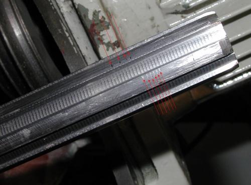
The only thing I could think of that would cause this would be the driven spindle shaft hitting a sharp edge inside the belt drive tube/shaft where the mating driving splines are. Even though the ends of the splines are chamfered they do still have an "edge" to them. And my mill has always had a slight rattle sound to it when its running because there is some backlash between the splines. But put a heavy cut on a flycutter.... ho-lee-cow! 
I cleaned up all the parts and then smoothed out the nicks/burrs on the spindle splines. Holding the drive tube over the spindle I found I could rock it back and forth a bit - top to bottom. Looking further I see that the drive spindle (tube) only has splines in in the center portion of the tube. The bottom of the tube has an oversize counter bore in it for the first 2 inches, then there is 2 inches of splines above that. The top 3-1/2 inches of the tube is also counter bored. I measured the parts and found there is a difference of .070" between the OD of the splines and the ID of the counter bores in the tube. 
I'm thinking that would account for the nicks in the splines if the driven spindle is being whipped around inside the tube and flexing because of too much clearance. Bending the spindle would cause the shaft to dig in to the edges of the splines in the center of the tube. Maybe? 
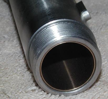
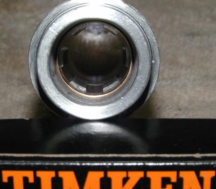
At any rate I turned some sleeves out of some graphite filled bronze rod (lots of expensive swarf there!) to take out some of the excessive clearance and hopefully hold things in line better. The sleeves are .030" wall thickness so that leaves me with .010" clearance (total) for the splines to run in. At least I hope so.
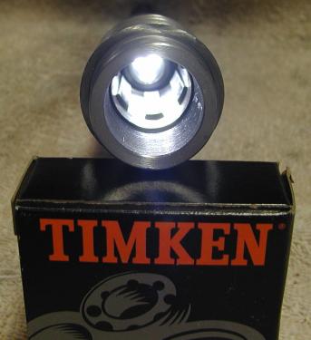

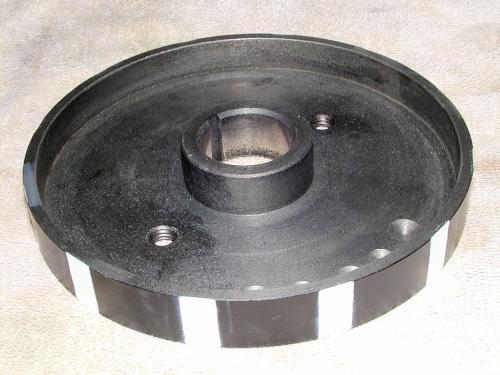
The spindle brake drum was slightly modified by cutting some flats around the OD to serve as an encoder wheel for a MachTach display. While the brake drum was off I also drilled and tapped it for 2 Helicoil inserts. This way if I ever need to touch-up the paint on my "encoder" I can use a stud-type gear puller to get it off instead of having to pull the entire drive spindle out to get at it.
Got the drive spindle assy back together with new (sealed  ) bearings, ready to go back into the mill. Still need to work on a mount for the IR speed sensor though. Not much room to work with.

Willie
|


![[Image: IMG_2041.jpg]](https://lh3.googleusercontent.com/-Enw9lLhfvDk/Vrke3bwvh4I/AAAAAAAADlI/iwHdDne3UEc/s1280-Ic42/IMG_2041.jpg)
![[Image: IMG_2042.jpg]](https://lh3.googleusercontent.com/-2h8fUOPLt_M/Vrke3swn_yI/AAAAAAAADlM/SbY2eaTuBqQ/s1280-Ic42/IMG_2042.jpg)

![[Image: IMG_2045.jpg]](https://lh3.googleusercontent.com/-_jaQyR1VD1o/VrlzmUzFpYI/AAAAAAAADlk/LU5y4o9SZrQ/s1280-Ic42/IMG_2045.jpg)
![[Image: IMG_2046.jpg]](https://lh3.googleusercontent.com/-9YZdhsuPjl8/VrqXQatj1PI/AAAAAAAADmE/ZM4hulElkIo/s1280-Ic42/IMG_2046.jpg)
![[Image: IMG_2047.jpg]](https://lh3.googleusercontent.com/-I8RfkH7x3eI/VrqXQU6P7NI/AAAAAAAADmE/FGh98MY7VcQ/s1280-Ic42/IMG_2047.jpg)


 ) bearings, ready to go back into the mill. Still need to work on a mount for the IR speed sensor though. Not much room to work with.