Hi Guys,
Here are some more pictures, I will try to give an explanation as I go along !
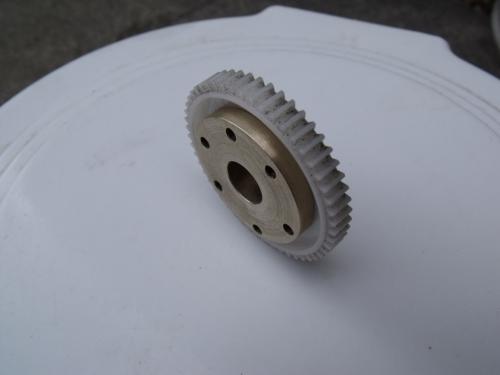
This is the brass bush inserted into the plastic gear. These pictures were taken before the keyway slot was put in.
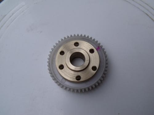
This is the brass bush inserted into the plastic gear. These pictures were taken before the keyway slot was put in.
The support ring is behind the plastic gear. This ring is tapped for the M3 screws used to hold the parts together.
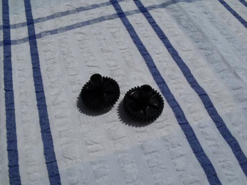
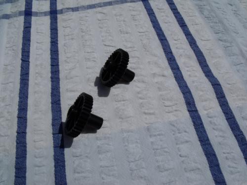
These are the small tumbler gears. They just happened to have the same teeth to fit the large gear and the one on the wiper motor shaft. These gears were all salvaged from various pieces of equipment, mainly printers and photocopiers.
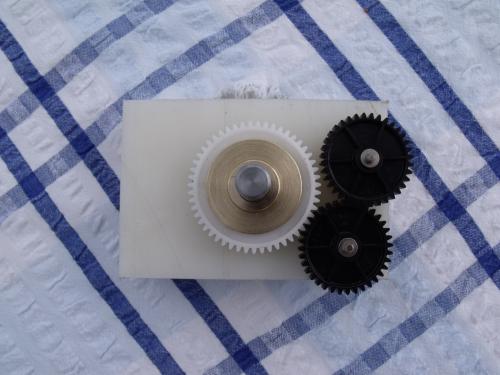
This is a mock up when I was deciding where to mount the two gears.
Note that they are shown on a 12 mm thick Nylon plate. It was this that I used for the tumbler mechanism.
One thing that I should mention, is that I did not remove or replace the left hand end cheek of the mill table ! But I did use the two screw holes securing the end cheek to mount the aluminum plate that supports the table drive.
That is a dummy shaft supporting the large gear.
The end cheek of the mill table has boss on it that holds the bearings for the leadscrew. The outside of that boss is very convenient for using as the support for the tumbler mechanism. The plastic plate sits on that boss very nicely, allowing full movement of the tumbler.
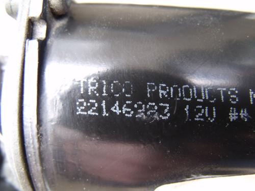
This is the "Trico" Window wiper motor that I used.
It is a dual speed motor, it uses the motor frame as the common positive connection. I have mine wired on the slowest speed. However it is rarely powered at more than eight or nine volts and more often at five or six. It really depend upon what I'm machining. I do put the full 30 volts on the motor for fast traverse.
In use the motor can take several amps in fast traverse but in normal use only a couple of amps.
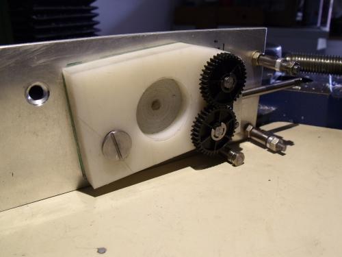
In this picture you can see the 3 mm aluminum plate used to secure the drive mechanism to the end of the mill table along with the mounting pillars that are used to support the wiper motor mounting plate, also 3 mm thick. You can also see one of the screw holes where I used a countersunk M6 screw into the end of the mill table.
I used a dummy shaft in order to decide where to drill and thread a large (M8) shoulder screw. This screw also prevents the tumbler lever plate from falling off and also sets the amount of movement of the tumbler.
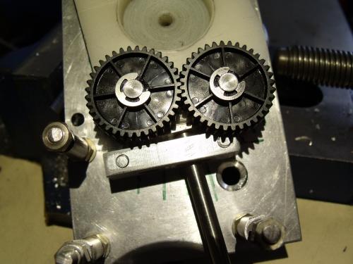
In this picture you get a better view of the tumbler mechanism and the dog clutch lever.
I'll post some more pictures later.


 solution: