Posts: 8,891
Threads: 320
Joined: Feb 2012
Location: Arizona/Minnesota
(05-04-2023, 09:35 PM)Vinny Wrote: (05-04-2023, 08:59 PM)EdK Wrote: No bench test for me today. I spent most of the day trying to figure out why the Arduino IDE couldn't see the Nano board plugged into my Linux computer. Got it working now so it's time to dive into doing PWM with the Nano board.
Ed
Permissions?
No, it ended up being a conflict with the port being used by my USB keyboard and the USB-RS232 chip on the Nano. A program called "britty" that's used by the keyboard had to be uninstalled to fix the problem. That program is only used for people with sight impairment so removing it had no affect on the keyboard usage for me.
Ed
Posts: 798
Threads: 52
Joined: Mar 2012
Location: Rochester, NY
The following 2 users Like rleete's post:
EdK (05-05-2023), Vinny (05-05-2023)
Have you ever made a boneheaded move that actually turned out in your favor?
7 months ago, I was making the frame for the Mrpete222 vertical engine and snapped off an endmill. My fault, there was way too much chatter, and I didn't back off quickly enough. Well, that prompted me to completely readjust the entire mill, tram the head and tighten the gibs. I got it working much better than before (that experience thing really pays off!), but I still had excessive backlash on the x axis, while the y axis play is nearly imperceptible. That was the impetus for me to make the power feed. Mill in one direction, return under power. Rinse and repeat.
So, as I'm working on this project, I had to reassemble the table. Again, I noticed the extremely excessive backlash. Like nearly .1" of play. Well, it turns out that the leadscrew nut has 2 set screws holding it in place. I swear I didn't touch them when adjusting before. They were both backed out and the nut was just sliding around in the slot. I don't believe they've ever been tightened properly. I simply snugged them down, and now the mill is better than it's ever been.
Full of ideas, but slow to produce parts
Posts: 8,891
Threads: 320
Joined: Feb 2012
Location: Arizona/Minnesota
Good find. I have about .007" of backlash in my X axis and I haven't quite figured out what's causing it. I tightened the screw on the nut that's suppose to reduced the backlash but it didn't seem to help much. Maybe I'll get lucky like you did when I tear it down to install the power feed.

Ed
Posts: 798
Threads: 52
Joined: Mar 2012
Location: Rochester, NY
I've decided to go with a slightly different configuration than I originally planned, and I am waiting on some tools I ordered to make the new parts.
Full of ideas, but slow to produce parts
Posts: 8,891
Threads: 320
Joined: Feb 2012
Location: Arizona/Minnesota
Any progress on this? Curious to see what you come up with.
Ed
Posts: 798
Threads: 52
Joined: Mar 2012
Location: Rochester, NY
I haven't gotten any shop time in a couple of weeks. Busy time of year for me.
Full of ideas, but slow to produce parts
Posts: 9
Threads: 1
Joined: Feb 2024
Location: North Yorkshire, UK
The following 3 users Like BaronJ's post:
JScott (02-28-2024), EdK (02-28-2024), Vinny (02-28-2024)
02-28-2024, 09:32 AM
(This post was last modified: 02-28-2024, 09:35 AM by BaronJ.)
Hi Guys,
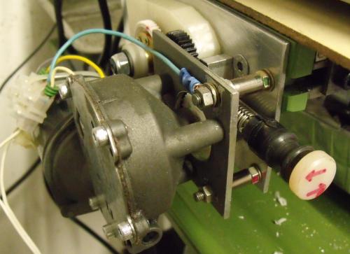
Some time ago I made a power feed for my mill table ! I also used a window screen wiper motor, salvaged from a scrap yard car. I actually have a couple of them that I also salvaged. Note that there are both left hand and right hand ones. I use a variable voltage/current power supply to feed my motor. It can supply 0 v up to 30 volts at up to 5 amps. The fact that the power supply is fully metered is very handy, because you can monitor the performance and progress of the machining.
I used gears to drive the leadscrew and added a Tumbler Gear mechanism, so I can have forward neutral and reverse movement of the table. Part of this is because I discovered that the window screen wiper motor is intended to run in one direction only, so reversing the power supply polarity to make it run in the opposite direction could create a future problem.
All the gears are plastic ones salvaged from printers and photocopiers. Only one gear needed extensive modifications to make it suitable for driving the leadscrew. I didn't make any modifications or changes to the mill leadscrew. I did make a new hub to replace the table handle on the left hand side. I retained the handle on the right hand side because it was convenient for traversing the table by hand when the tumbler gears were in neutral.
One advantage I did find was that since I had covered up the table locking screws when I fitted the DRO scale to the table front, was putting the power feed into gear would stop the table from moving when using the front hand wheel to cut an edge.

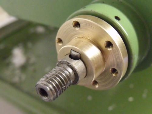
This is the new hub that I made to replace the left hand handle.

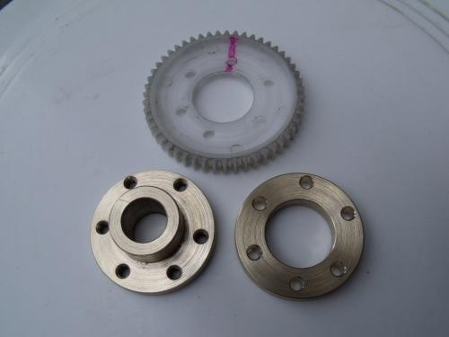
The plastic gear is bolted onto this hub.

The brass ring was made for the purpose of reinforcing the clamping of the plastic gear.
Posts: 8,891
Threads: 320
Joined: Feb 2012
Location: Arizona/Minnesota
Nice work BaronJ!


to the forum.
Ed


 to the forum.