5 Cylinder Radial
#21
Thinking out of the box here, the crank could be extended at the rear and drive the distributer with a set of helical gears, or am I thinking wrong? You would need to redesign the crank to have just a tad for the extension.

"Billy G"
Reply
Thanks given by:
#22
I think that is possible Billy But it will take up a fair bit of room and push the oil tank back a bit. that I now think I have made to large already I think about half a pint of oil will be more than enough, also it will make servicing the distributor almost impossible without striping the tank off.
I will draw up the cam drive and see what it looks like.
Tomorrow we are off to the boat if it's not windy, and stay the night Smiley-dancenana

Brian.
Brian, proud to be a member of MetalworkingFun since Sep 2012.
http://briansworkshop.weebly.com Welcome
Reply
Thanks given by:
#23
 At last I think I am getting somewhere.
Again this drawing is a montage of all five cylinders. So what is new .

The cylinder and rod are now longer to reduce con rod angularity and allow a better proportioned master rod.

Oil tank is now shorter and will form the mounting for the engine.

Plunger oil pumps driven from the accessory shafts on number 2&5 cylinders, spit and hope lube system.

Distributor on number 3 cam shaft trigger unit on number 4 cam shaft.

Natural gas cab mounted below crank case feeding annular chamber in nose piece.

Prop hub to take 24X12 prop (possibly)
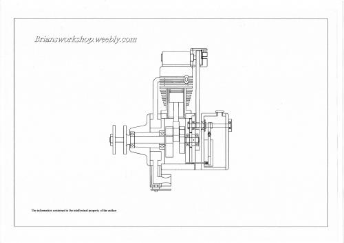
   

More work to do on tensioner for belts  and determining the position of the head studs and the angle of the exhaust port. ETC
But as I do not intend to start cutting metal until the winter I have plenty of time.

Brian Smiley-dancenana
Brian, proud to be a member of MetalworkingFun since Sep 2012.
http://briansworkshop.weebly.com Welcome
Reply
Thanks given by:
#24
What a fantastic project.
Have you considered using hall-effect ignition? Takes away the need for a distributor. Even electronic fuel injection rather than a carburettor? You could make that thing roar from a remotely mounted control panel. There are downloadable electronic schematics to accomplish both.
Lathe (n); a machine tool used in the production of milling machine components.

Milling Machine (n); a machine tool used in the production of lathe components.
Reply
Thanks given by: Brian
#25
Hi Pete
Thanks for the heads up on hall-effect, I had discarded the idea because of having to use 5 coils and trigger units, but you made me do more research and I have found coils for £6 each  and a home build circuit for the trigger unit so I may think again about using H-E  
The fuel supply for this engine will be Propane, I have had great success with the carb I made for my  32x40 engine So I am continuing  with this engine.  
Thanks again, information is always useful.

Brian. Smiley-dancenana
Brian, proud to be a member of MetalworkingFun since Sep 2012.
http://briansworkshop.weebly.com Welcome
Reply
Thanks given by:
#26
Brian I just had a look at your youtube video of the 32x40 engine running, a beautiful thing. Looking forward to the video of the radial starting up!
Lathe (n); a machine tool used in the production of milling machine components.

Milling Machine (n); a machine tool used in the production of lathe components.
Reply
Thanks given by:
#27
Thanks for the comments Pete, I am still working on the Highlander as we now call it Just tidying and making a new gas supply. from a old propane blow lamp ( Pic's will follow ).
The only problem with using the name Highlander is that on U tube the video gets placed wrongly.
The Radial will take a back seat for the summer, While I am on the boat for the next few months Getting ready for our
Giro around Sicily or where ever the wind takes us . Life is hard when you are retired. Graft --Graft -- Graft. not a moment for real work
Contact from Wi Fi in ports may be limited. we will see when the time comes.

Brian.
Brian, proud to be a member of MetalworkingFun since Sep 2012.
http://briansworkshop.weebly.com Welcome
Reply
Thanks given by:
#28
Bad weather has caused us to be ashore for a while  so the CAD has taken a bashing, not a lot is left of the original design

The cylinders are longer --stroke shorter-- crank case larger--The heads have had a total rethink--cylinders are now of steel rather than iron liners in alloy cylinders --oil  pumps are now Co Axial driven of no1 accessory shaft.-- we now have tensioners for the cam belts.
etc--etc.
 For the ignition it looks like individual hall triggers on each cam with small coils from the scrap yard ( on plug type modified to mount remotely).
When I start the build I will follow Colin Chapmans (Lotus) advice --Remove weight and Add lightness.


Working drawings  now need to be done for each component so that just may take a while.

Brian. Smiley-dancenana
Brian, proud to be a member of MetalworkingFun since Sep 2012.
http://briansworkshop.weebly.com Welcome
Reply
Thanks given by:
#29
Hi Brian,

How do you plan on opening the valve(s)? I don't see any cams or linkage.

Tom
[Image: TomsTechLogo-Profile.png]
Reply
Thanks given by:
#30
(05-25-2015, 03:03 PM)TomG Wrote: Hi Brian,

How do you plan on opening the valve(s)? I don't see any cams or linkage.

Tom

There's a belt-driven overhead camshaft on each cylinder Tom. I'd love to see some detail on the belt drive and tensioner arrangement.

I'm picturing a home-built Sopwith Pup with a home-built radial engine up front....
Lathe (n); a machine tool used in the production of milling machine components.

Milling Machine (n); a machine tool used in the production of lathe components.
Reply
Thanks given by:


Users browsing this thread: 5 Guest(s)