Posts: 437
Threads: 24
Joined: Sep 2012
Location: Sicily
The following 1 user Likes Brian's post:
EdK (06-27-2015)
06-27-2015, 06:34 AM
(This post was last modified: 06-27-2015, 06:39 AM by Brian.)
Hi All
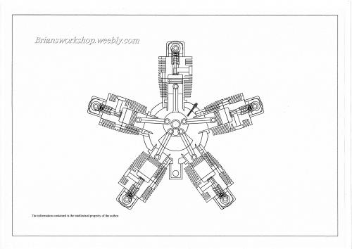
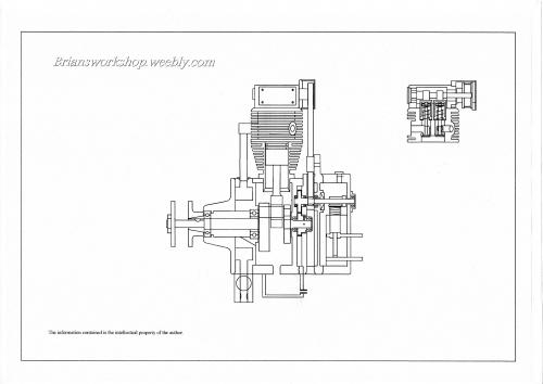
After long hours at the computer the working drawings are coming together, it's amazing what you have to change to accommodate fixing screws etc as I go along.
The engine mounts are now built into the design so they don't look like an after thought. also I am also working on the jigs necessary. and trying to make them multi use. for the lathe and mill.
I have settled on having Individual hall sensors on each cam and separate mini coils so perhaps later by using two magnets I will be able to have auto advance.
As some of you will know The master rod causes timing problems on radial engines because only number one big end follows a circular path. all the others are slightly out at TDC ( not exactly 170° apart ) I am hoping that using separate cam shafts I will be able to get the valve and ignition timing correct .
Tooling for the lathe and mill is under review , a co axial indicator for the mill will be the on the cards.
Brian.

Posts: 3,799
Threads: 184
Joined: Jun 2012
Location: Farmington Hills, Michigan
Hi Brian,
Back to the valve train. So you'll be using some sort of planetary gear to drive inner sprockets and the cams will be keyed to the shaft in proper orientation to get the timing correct?
Nice job on the drawings.
Tom
Posts: 437
Threads: 24
Joined: Sep 2012
Location: Sicily
Hi Tom
I had to dig into old drawings to find this one, but the gear train remains the same.
The centre gear pined to the crank drives the 5 intermediate gears at 1-1 ratio. the secondary gears are cut in one piece with the shafts. the small timing pulley is pinned and locktited to this shaft. the belt belt ratio up to the cam is 2-1 .
The camshaft is one piece ( as in my horizontal engine ) fixed to the pulley with a end nut and 2 pinch screws allowing the valve timing to be set . ignition timing is set by rotating the end of the cam pulley cover that will have a hall effect sensor located in it.
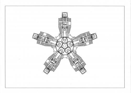
I cant get a 2-1 ratio on the gears inside the case because the larger gears will overlap each other if the number of cylinders had been even it is possible to go one in, then one out, but with 5 gears you end up with two gears wanting the same space
Brian.

Posts: 437
Threads: 24
Joined: Sep 2012
Location: Sicily
With the sounding of trumpets and the beating of drums the first material was cut today.
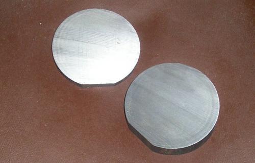
These two disks will form the Jig for all the crank case work, the engine has been designed so that all the sections have the same diameter registers, also the jig will be transferable between the rotary table and the lathe face plate, located by a central spigot, so set up time will be kept to the minimum.
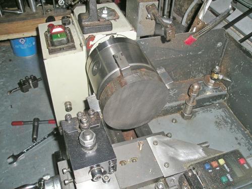
I can just get the 100mm blank into my 4 jaw self centring chuck so work will start tomorrow,
Up Up and away Brian

Posts: 968
Threads: 67
Joined: Apr 2015
Location: Australia
Watching

Lathe (n); a machine tool used in the production of milling machine components.
Milling Machine (n); a machine tool used in the production of lathe components.
Posts: 437
Threads: 24
Joined: Sep 2012
Location: Sicily
The following 1 user Likes Brian's post:
EdK (07-15-2015)
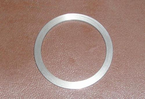
OK so now we have the first part, this ring is the conversion ring for the jig, it serves two purposes .
It is 90mm od and serves as go-no go ring for all the female registers on the crank case and the second part of the jig,
It also converts the jig from female register to male,
Brian

Posts: 218
Threads: 9
Joined: Dec 2014
Location: Bristol Ct. USA
Extremely good thinking on your part Brian. The male and female connections are about as important as it gets as far as fit up is concerned.
"Billy G"
Posts: 437
Threads: 24
Joined: Sep 2012
Location: Sicily
The following 3 users Like Brian's post:
EdK (07-22-2015), f350ca (07-22-2015), Mayhem (07-23-2015)
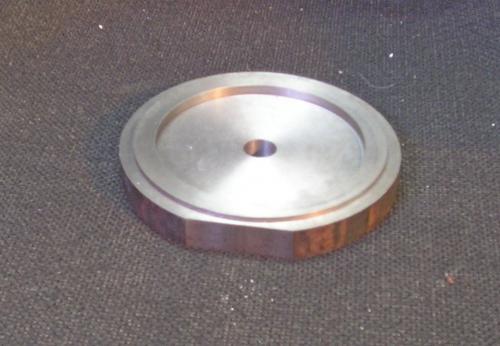
The next stage was to machine the jig base-the central hole for the spigot and the 90 mm register being machined without disturbing the work to ensure concentricity. I have ordered two soft arbours MT3 for the lathe and MT2 for the rotary table
to be machined 12mm to fit the central spigot.
Photo shows the work so far with the conversion ring in place.
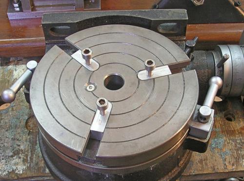
The next problem is to hold the jig and the work radially, so when a part is placed in the jig 0° is always correct.
To this end I have made new T slot nuts for the rotary table that fit perfectly and the threads are on centre and straight,
The holes in the jig will be sized to just take the bolts. I think this will solve the problem of locating the jig the work will be retained by a centre draw bar and 5 studs that locate in the position of the accessory shafts.
Slowly slowly, Brian.

Posts: 437
Threads: 24
Joined: Sep 2012
Location: Sicily
The following 2 users Like Brian's post:
f350ca (08-09-2015), stevec (08-10-2015)
Squaring up the rotary table on the mill. I noticed that at 0° the T slot opposite the zero was out of square by 2° 30'
I shifted the pointer to correct this, Prior to drilling the jig.
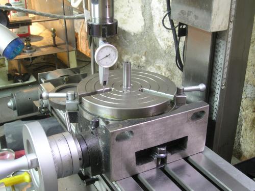
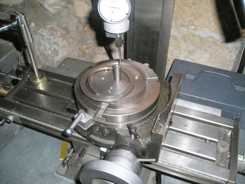
The jig was located on the spigot and drilled with 3 holes that fit the table and the nose of the lathe.
5 extra holes where added that will match the position of the accessory shafts in the case for fixings.
It all looks good to go, so the next job is the jig for the cylinders.
Brian


![[Image: TomsTechLogo-Profile.png]](http://tomstechniques.com/wp-content/uploads/2013/11/TomsTechLogo-Profile.png)
