Tractor loader rebuild
#21
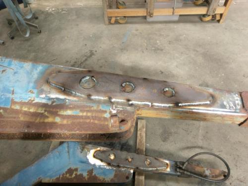
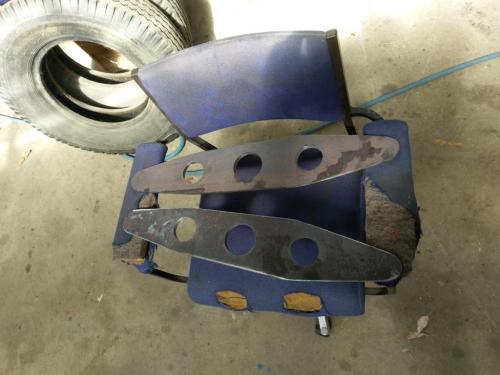
A little bit more progress, I made the fish plates for the outside of the arms to reinforce where I have welded the ends back on. Also made a smaller pair of plates for the inside of the arms, these are more limited because of the cross member and one of them having to work around the oil outlets for the third function. I got one of each welded on, forgot to take any photos but this one of the two longer plates. They'e just under 600mm long, cut from 150 x 10mm flat bar.
   
Lathe (n); a machine tool used in the production of milling machine components.

Milling Machine (n); a machine tool used in the production of lathe components.
Reply
Thanks given by:
#22
Nice. What did you use to cut the plates and make the holes? They look nice enough to suggest a CNC plasma cutter.
Reply
Thanks given by:
#23
(12-01-2019, 08:45 AM)arvidj Wrote: Nice. What did you use to cut the plates and make the holes? They look nice enough to suggest a CNC plasma cutter.

The closest I ever expect to get to a CNC plasma cutter Arvid; a 5" angle grinder and a holesaw! Cleaned up the curves on my disc sander.
Lathe (n); a machine tool used in the production of milling machine components.

Milling Machine (n); a machine tool used in the production of lathe components.
Reply
Thanks given by:
#24
Spending a little more time on this today, got the four reinforcing plates at the front welded on.
   
The inner r/h one is a bit of a dog's breakfast with having to work around the hydraulic fittings.

Having made some curved no-stress plates for the front end of the frame, I'm not sure I can leave these things in place on the back end.
   
The highest stressed part of the whole machine I would think; looks like it has been bent and straightened at some time. I think I'll have to cut all this mess off and make some longer fish plates for inside & outside of both arms.
Lathe (n); a machine tool used in the production of milling machine components.

Milling Machine (n); a machine tool used in the production of lathe components.
Reply
Thanks given by:
#25
Project creep. We've all been there.

Fix it now, or you'll never be quite satisfied with it. It may work, but it will bug you forever.
Full of ideas, but slow to produce parts
Reply
Thanks given by:
#26
I got three of the four dodgy reinforcing plates cut off last night. This is what was behind one of them
   

the most predictable structural failure. The attachment point for the lift rams is right at the end of the big gussets, which finish with a sharp internal angle.


I'll add a pair of 600mm fish plates to each arm, similar to what I have done on the outside at the other end, centered over the lift point. My neighbours must be getting used to the sound of my angle grinders anyway.
Lathe (n); a machine tool used in the production of milling machine components.

Milling Machine (n); a machine tool used in the production of lathe components.
Reply
Thanks given by:
#27
G'day all, haven't been around for a while- we were without internet at home for over a month. Long story. I have managed to make a little progress on the loader but not nearly as much as I would have liked.
Made and attached the fish plates for the stress point over the lift ram attachment. Pretty much the same as the other end- 600mm long 10mm thick- matching plates to the inside and outside of the arms at this end as there is no cross member in the way.
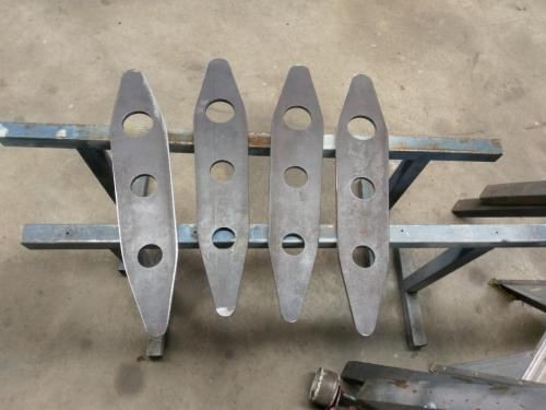


I've been working on the line-boring setup as time permits. got a length of 25mm bright shaft, cross drilled in a couple of places for a 3/8 round HSS cutter and a grub screw to locate same. Four flanged housings with self-aligning bearings will carry the shaft.
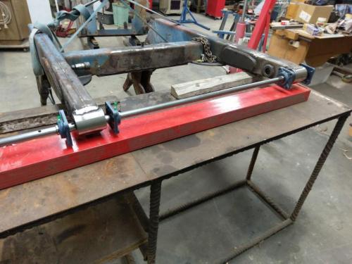
   

I've been musing over how best to provide power and feed to the line-boring shaft and after many various setups in my head, finally settled on using the lathe for both power and feed. I'll set up the steel bench behind the lathe and take power from the back end of the spindle, using a tractor PTO shaft to connect to the boring shaft. The PTO shaft sliding joint will allow for the necessary longitudinal movement of the shaft for the boring operation, and I can link the shaft to the apron of the lathe to power the feed (that will become clearer as i progress with the setup).
I've made a PTO output for the spindle, this will be held in the chuck and extend out the back of the spindle. I had a suitable length of 38.5mm round stock, turned one end to the major diameter of the splines, with an extended nose turned to the minor diameter for holding in the dividing head and touching-off with the cutter,
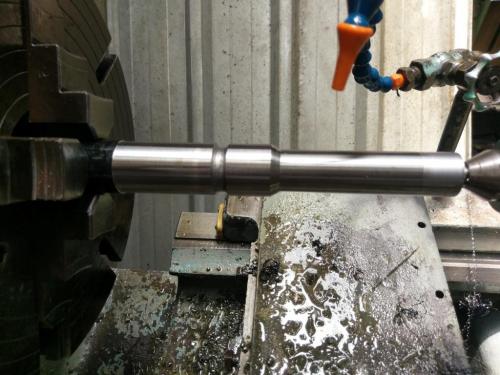
   
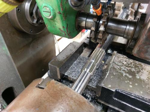
There is a proper cutter for this job that takes out the space between the splines in one pass, but I don't have it (I checked). So I used a pair of cutters with a spacer, the thickness of the spline, between. I didn't have a pair of cutters or a spacer the right thickness either, but the surface grinder took care of that. I found two cutters of the same nominal size, ground them to identical thickness so that they would be on centre after touching-off on both sides of the workpiece, then sharpened them both to the same diameter. I had to take over .025" off every tooth on one of the cutters to bring it down to the diameter of the other. Took ages but I got there.
The shaft is too long to use the tailstock with the dividing head, so I set up a v-block and clamp to hold the back end against the cutting forces.
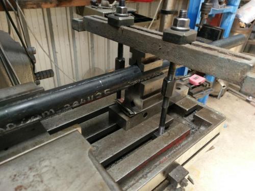
   

Using the mill in horizontal mode for the first time since the Bridgeport conversion. One pass with the cutter pair for each of the 6 splines. I was too lazy to take the vises off the mill, they are not involved in this job.
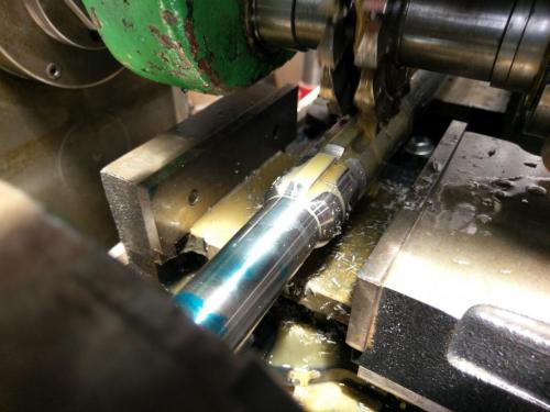
   
   
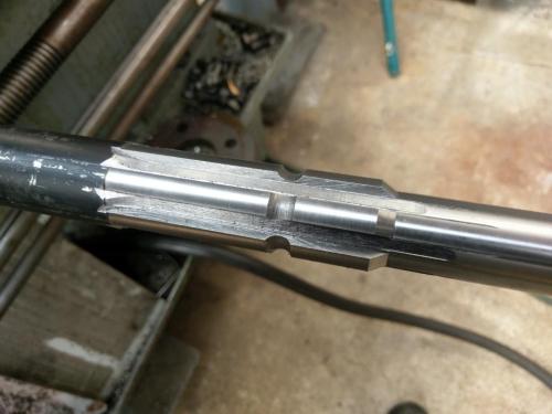
this leaves a ridge down the centre between the splines that has to be milled off. The PTO shaft specs show a minor diameter, but apparently this is not important as the female engages on the major diameter, so the shaft can be milled flat between the splines. I had a cutter of appropriate thickness to knock off the ridge, indexed the DH half way between the splines and ran it through.
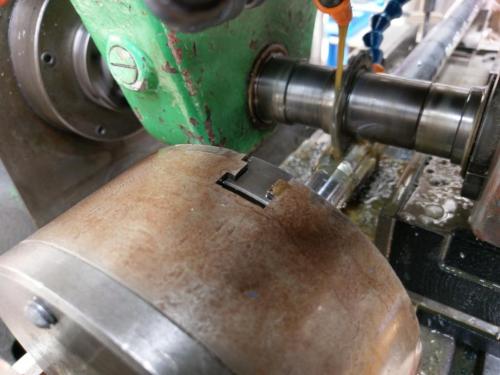


The long nose was taken off in the bandsaw. I'll face the end in the lathe (have the blank for the other end of the job in there at present).
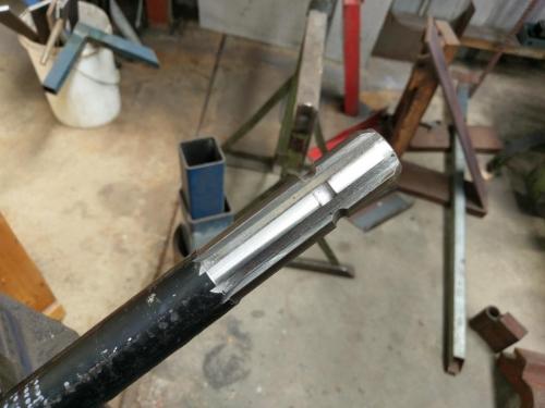
   

Due to the way this job had to be held in the DH, I was unable to check the splines for fit until the extension was cut off, so there was no opportunity to tweak the fit in the mill. I have one rusty old PTO shaft that won't slide on and one new PTO socket that goes on nicely. I'll be using the long driveshaft off my slasher which is almost new, haven't checked it for fit yet. Hopefully it's just the rust in the other that prevents it going on- it's been lying outside for years- otherwise a bit of file work may be necessary.

The driven-end adaptor blank is in the lathe at present, it'll be bored at the back end to fit on the 25mm boring bar. Waiting for a reamer to arrive to finish the bore so I can take it to the mill to spline it. That one will be done using the DH tailstock, with just enough nose to touch-off for cutter depth.
Lathe (n); a machine tool used in the production of milling machine components.

Milling Machine (n); a machine tool used in the production of lathe components.
Reply
Thanks given by:
#28
A little more progress on the line-boring setup;
I finished the PTO output shaft  for the lathe.
This end is held in the chuck
   
and this bit sticks out the back end of the spindle
   
There's a tapered spigot that centres the back end in the spndle bore, forgot to take a photo. Nothing special there.

The other important bit is the driven end PTO adaptor. Splined one end and bored 25mm at the other end.
   
I used the shaper to cut an internal keyway in the adaptor. Don't know what I'd do without it.
   
Have to have a hole at the end of the keyway to run the tool into.
   
Cut a keyway into the shaft
   
A couple of grub screws to hold it in place and a bit of oversized key steel ground for a custom fit on the surface grinder.
   

I had to do a bit of work on both splined adaptors with a die grinder to get the driveshaft to slide on. Must remember to grind my horizontal milling spacer a tad thinner next time I do this. Probably had to take less than a thou off the splines for a fit.
Finally got the PTO shaft to fit both ends.


That's chewed up my days off this week. I'm hoping I may actually do the boring next week. I have to set up the bearing mounts to carry the boring shaft, hopefully that shouldn't be too difficult.
Lathe (n); a machine tool used in the production of milling machine components.

Milling Machine (n); a machine tool used in the production of lathe components.
Reply
Thanks given by:
#29
Thats an incredible set up Pete.
Haven't tried a blind keyway on the shaper yet. Will have to give that a go.
Free advice is worth exactly what you payed for it.
Greg
Reply
Thanks given by:
#30
Your problem solving skills demonstrate the difference between an all around machinist/toolmaker and a machine operator. Thumbsup
Reply
Thanks given by:


Users browsing this thread: 8 Guest(s)