11-13-2019, 07:16 AM
I've been sorely missing the front-end-loader off my tractor since I took it off early last year (I think) to do all the overhaul work on the tractor. Rebuilding the loader has finally made it to the top of my to-do list. A few photos to give an idea what I'm dealing with;
This is the main loader frame, complete with 40 years of farmer repairs and alterations.
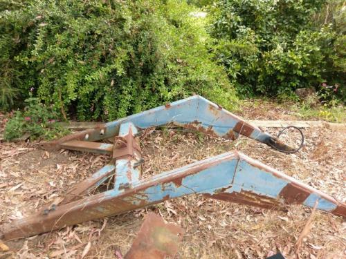
I don't have any photos of the rest of the frame, I'll try and remember to take some of the other bits. There's a large channel section that bolts up to the underside of the tractor, plus two big frames that sit on the channel with braces that go to the rear axle and the tombstone housing at the front of the engine. The side frames are pretty much ok although I'll need to re-do the mounting for the control valve, but most of the work to be done involves repairs and modifications to the frame shown above. I plan to change the hydraulic setup from a single tilt cylinder mounted to the middle of the bucket, to a more modern style arrangement with a tilt cylinder on each side, a dual linkage arrangement which increases the rotation angles of the bucket, and a quick-attach setup to make swapping the bucket and other implements easy as I plan to obtain (or build) a grapple attachment for it once the loader is operational again. I picked up a 'new-old-stock' John Deere loader bucket from a bloke who used to own a JD dealership, so I'll build the quick-attach setup based on that system. In the photo below, the bucket is sitting upside down so it doesn't fill up with rain, but you can get the idea of the attachment system.
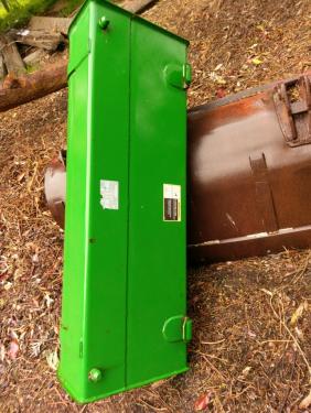
That's the old rusted-out and torn-up bucket that the new one is sitting on; the new one is quite a bit smaller but large enough for my purposes.
I got the frame components into the shed and assembled them and got everything level. I scratched my head for a while over how I was going to get the necessary machining done on the front ends of both of the loader arms, in the end I decided to cut the ends off so I could work on them in the mill, then weld them back on and fishplate them. I'm confident that my welding is better than anyone else who has been near this thing over the course of it's life. I spent most of one day, about 15 5" cutting discs and a few grinding discs and flap wheels getting rid of all the unnecessary bits, then got to marking out ready to cut the arms.
I found a centreline along each of the tapered arms and scribed a line, then centre-punched at 100mm intervals as a reference for when the ends go back on
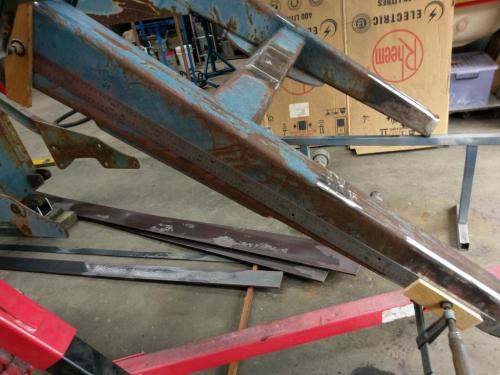
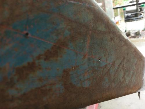
One more cutoff disc and the point of no return has been reached.
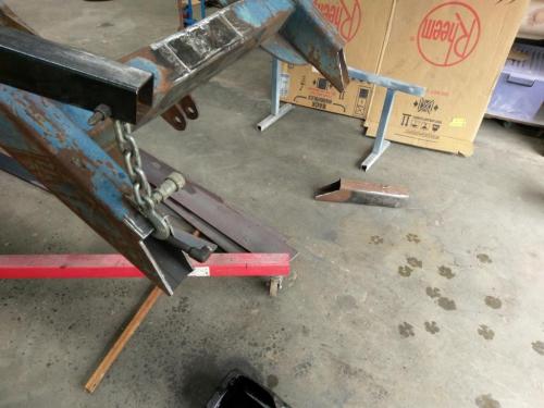
I took a drive to a John Deere tractor dealership and asked nicely if I could take some measurements and photos of one of their loaders so I could get the geometry right for the dump linkage system. I'm sure there is a name for the system where the rams are connected to the bucket via a second arm and linkage, but I haven't been able to find what it is. It will hopefully end up looking something like this (from google images)
 loader hitch image.jpg (Size: 15.5 KB / Downloads: 149)
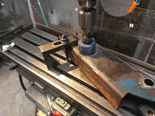
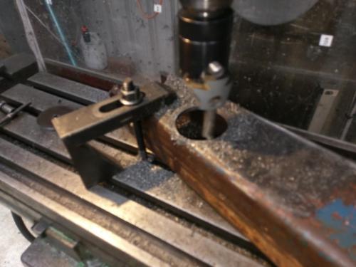
The pivot points for the front end of the ram will be a cylinder of 4140 just over 3" diameter welded across the end, bored to take a hardened bush which will accept a 25mm greasable pin. The second pivot point is also a barrel of 4140 welded through the arm 140mm further back (centre-to-centre). After some careful marking out to get everything as square as possible, I used a holesaw to rough out the holes and then stretched my 2" boring head to it's limit to make them round and centred on the right place.
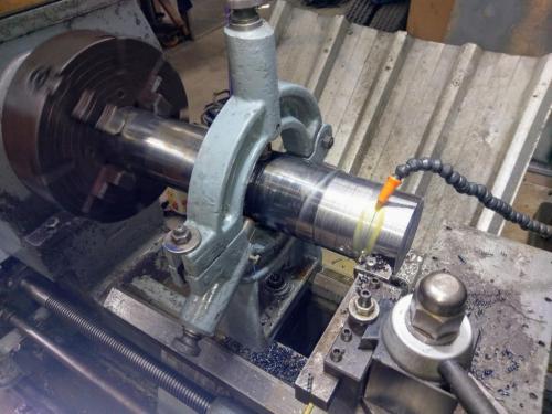
I don't like using the fixed steady in the lathe but I couldn't see an easier way of getting the barrels out of this chunk of 102mm 4140. I actually managed to get the steady set up nicely and didn't have the workpiece trying to walk out of the chuck as usual.
I've always had long, stringy swarf when I've turned 4140 but I've been reliably informed that if I push it harder it will actually break a chip. I worked it much harder than I have before and with a little trial-and-error got my swarf from this 10-footer
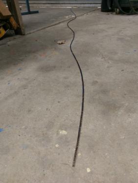
to this nice little pile of blue sixes and nines.
![Filename: IMAG2554[1].jpg
Size: 123.97 KB
11-13-2019, 07:10 AM](attachment.php?thumbnail=16363)
Had to keep changing up gears as the diameter shrunk or it would quickly revert to the long stuff.
That's about as far as I've got so far, plenty more to do.
This is the main loader frame, complete with 40 years of farmer repairs and alterations.
I don't have any photos of the rest of the frame, I'll try and remember to take some of the other bits. There's a large channel section that bolts up to the underside of the tractor, plus two big frames that sit on the channel with braces that go to the rear axle and the tombstone housing at the front of the engine. The side frames are pretty much ok although I'll need to re-do the mounting for the control valve, but most of the work to be done involves repairs and modifications to the frame shown above. I plan to change the hydraulic setup from a single tilt cylinder mounted to the middle of the bucket, to a more modern style arrangement with a tilt cylinder on each side, a dual linkage arrangement which increases the rotation angles of the bucket, and a quick-attach setup to make swapping the bucket and other implements easy as I plan to obtain (or build) a grapple attachment for it once the loader is operational again. I picked up a 'new-old-stock' John Deere loader bucket from a bloke who used to own a JD dealership, so I'll build the quick-attach setup based on that system. In the photo below, the bucket is sitting upside down so it doesn't fill up with rain, but you can get the idea of the attachment system.
That's the old rusted-out and torn-up bucket that the new one is sitting on; the new one is quite a bit smaller but large enough for my purposes.
I got the frame components into the shed and assembled them and got everything level. I scratched my head for a while over how I was going to get the necessary machining done on the front ends of both of the loader arms, in the end I decided to cut the ends off so I could work on them in the mill, then weld them back on and fishplate them. I'm confident that my welding is better than anyone else who has been near this thing over the course of it's life. I spent most of one day, about 15 5" cutting discs and a few grinding discs and flap wheels getting rid of all the unnecessary bits, then got to marking out ready to cut the arms.
I found a centreline along each of the tapered arms and scribed a line, then centre-punched at 100mm intervals as a reference for when the ends go back on
One more cutoff disc and the point of no return has been reached.
I took a drive to a John Deere tractor dealership and asked nicely if I could take some measurements and photos of one of their loaders so I could get the geometry right for the dump linkage system. I'm sure there is a name for the system where the rams are connected to the bucket via a second arm and linkage, but I haven't been able to find what it is. It will hopefully end up looking something like this (from google images)
 loader hitch image.jpg (Size: 15.5 KB / Downloads: 149)
The pivot points for the front end of the ram will be a cylinder of 4140 just over 3" diameter welded across the end, bored to take a hardened bush which will accept a 25mm greasable pin. The second pivot point is also a barrel of 4140 welded through the arm 140mm further back (centre-to-centre). After some careful marking out to get everything as square as possible, I used a holesaw to rough out the holes and then stretched my 2" boring head to it's limit to make them round and centred on the right place.
I don't like using the fixed steady in the lathe but I couldn't see an easier way of getting the barrels out of this chunk of 102mm 4140. I actually managed to get the steady set up nicely and didn't have the workpiece trying to walk out of the chuck as usual.
I've always had long, stringy swarf when I've turned 4140 but I've been reliably informed that if I push it harder it will actually break a chip. I worked it much harder than I have before and with a little trial-and-error got my swarf from this 10-footer
to this nice little pile of blue sixes and nines.
Had to keep changing up gears as the diameter shrunk or it would quickly revert to the long stuff.
That's about as far as I've got so far, plenty more to do.
Lathe (n); a machine tool used in the production of milling machine components.
Milling Machine (n); a machine tool used in the production of lathe components.
Milling Machine (n); a machine tool used in the production of lathe components.


