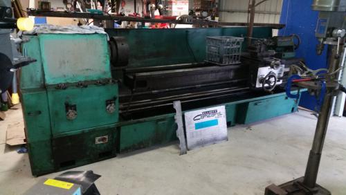
Elliott Concord 460 lathe
#61
Great work Darren. I can appreciate the electrical upgrade before applying power. Better to do it that get too excited and startup a bonfire rather than a machine.

I have a Pratt Burnerd chuck for my lathe and it's of extremely high quality. That one should serve you well.
Reply
Thanks given by: Mayhem
#62
Thanks Ken - I wasn't aware that they were the same manufacturer.  One thing I did note was that the concentric rings are marked in inch diameters.

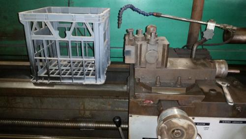
Thanks Pete - here are a couple of pictures with a good old Aussie milk crate for reference!  Also, in the holder is a 1" shank negative rake profiling tool gifted to me by Wrustle.


The clutches were actually a little more difficult to adjust that the instructions on the cover and in the manual lead me to initially believe.  First the drawing wasn't all that flash and the manual didn't even have a drawing!  Second, you need to have very little hands or very long fingers and third, you should grow an additional hand as well.  

You have to slide the knurled ring away from the clutch pack whilst navigating the copper oil line and the shaft in front.  Once the knurled ring has moved, you set the gap to 0.041" with a feeler gauge (or two if you don't have the correct one).  I only had bent end ones here, which complicated things.  My straight ones are in my other shop.

Reverse clutch ready for adjustment
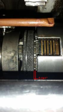
   

Forward clutch adjusted
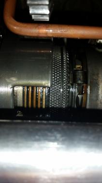
   

For some reason, I couldn't understand why the brake clutch pack was so difficult to adjust.  I couldn't even slide the knurled ring.  Then it suddenly dawned on me.  The instructions said to disengage the clutch, so when I adjusted the fwd/rev clutches, I had the spindle lever in the off position.  I left it in this position, not thinking (obviously), as the off position engages the brake Slaphead  Once the lever was put into fwd, the brake clutch was much easier to adjust.  Of note, the copper tubes ensure that the clutches are oiled continuously during use.

Normally, the next step would have been to put the rear and top covers back on and try the spindle.  However, my gasket forming goo is in my other workshop (with my straight feeler gauges), so I couldn't power her up.  However, the lever now remains in the reverse position, which it didn't do initially.  There also seems to be a more defined disengagement of the fwd/rev positions.  Of course, this could mean nothing under power...

Next, I turned my head to the cross slide and compound slide.  Looking at the rear of the cross slide, I think I have found where the taper attachment fits:
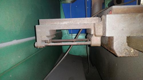
   

Looking ahead - I'm not sure how best to mount a DRO slide here, as the side of the cross slide is machined at an angle.  I have read that rear toolposts and other attachments were available for these lathes, and wonder if they were dovetailed, as both the front and rear sides are the same.
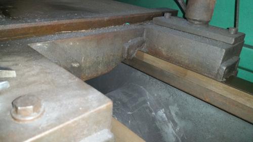
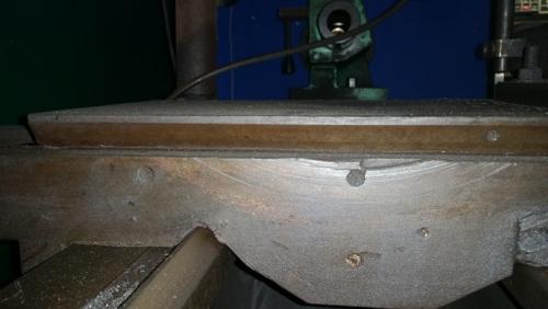


As the above pictures shows, there has been at least one decent crash on this lathe...  I will have to modify the crane mounting position to fit the scale to the rear of the cross slide.  I'm not even going to consider mounding it on the front, given that I have a following steady.

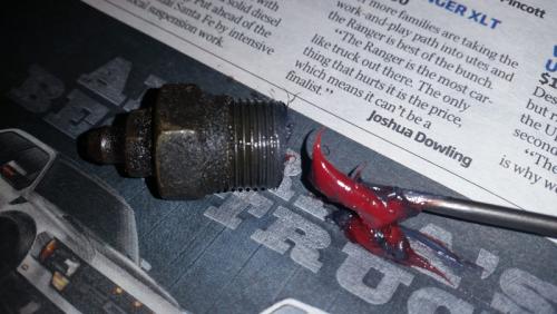
I have been throwing some of the fasteners and other small items into the tumbler today.  Last in was the OIL nipple on the front of the cross slide.  Why do people see these and assume they are for grease  Bash


Oh well, at least none of the handles have been broken on this, unlike my mill.
Hunting American dentists since 2015.
Reply
Thanks given by:
#63
That bracket for the taper attachment on the back the cross slide is a major component, as is the mating slide you have in the box. The third major part that may be the fly in the ointment is the block which connects from the end of the cross slide screw and stays stationary within that bracket in your photo. That mechanism follows the angled slide, pushing and/or pulling the cross slide in or out as it travels along the longitudinal axis. See anything that could make that connection in the bib of spares, or is that still there on the machine?

How much travel does that cross slide have as compared to the older lathe and the DRO scale you have? Given you now have a working mill, you should be able to make blocks for whatever adaptation you need. Remember my lathe's installation for the cross slide is partially along the side but also hangs out toward the back of the chip guard. It works.
Reply
Thanks given by:
#64
I said it before but that is a beast of a lathe. Thanks for posting the pictures and good job at cleaning up the electricals.

Ed
Reply
Thanks given by: Mayhem
#65
(05-24-2015, 08:43 AM)EdK Wrote: I said it before but that is a beast of a lathe. Thanks for posting the pictures and good job at cleaning up the electricals.

Ed

His ancient one is also a beast, but this one is a more refined, civil and controllable beast....with ten times the productivity capacity.

Darren, from the looks of it you have a standard faceplate for the machine. You just need to remove the four rods and plate that are fastened to it right now. What are the diameters of the 4 jaw chuck and the faceplate?
Reply
Thanks given by:
#66
I'm going to remove the chip guard in the not too distant future, which will give me better access to the rear of the cross slide. I haven't measured total travel yet, as fitting the DRO is the least of my concerns right now.

Looking at the info in the manual (p. 29) regarding the taper attachment, the "block" (14) is the missing part that attaches to the cross slide leadscrew. This doesn't look too difficult to make. Looking at the drawing, it appears to be a simple L-shaped bracket with a hole for the leadscrew to attach to and another to engage the pin on the top slide (15). The bottom slide (12) is one part that I am unsure of but it appears to be missing. However, there is a bolt at the bottom of the main body of the taper attachment that might be the point to which the connecting bar attaches to. If so then the drawing confuses me...

The exploded diagram for the cross slide (p. CP 28) shows that the leadscrew doesn't attach directly to the hand wheel but slides within a keyed sleeve. To me this suggests that there is no need to disconnect the screw from the cross slide when using the taper attachment. If I am correct, does this mean that I can leave the taper attachment in position, with the exception of the anchor bracket when not in use?

I wish they included actual photographs rather than the drawing, as I am unfamiliar with taper attachments. I will continue to study the diagrams but most of my efforts will be going on getting the feed working. Once done, then the real cleaning and looking at things like the taper attachment will become more serious.

I think you are correct Ken. There is a plate covering the front and the four rods are welded on. To be honest, I haven't really paid much attention but will look at it a bit more tomorrow. The chuck is 14" and the faceplate is 15"

EDIT: I just realized that the info on the taper turning attachment begins on page 28 of the manual Slaphead This makes more sense and confirms my observation of the telescoping leadscrew. It appears that the large part of the taper attachment in the bottom slide (12). So it may just be the aforementioned block that is missing.
Hunting American dentists since 2015.
Reply
Thanks given by:
#67
I am just wondering why you removed the big nameplate from the machine, and the threading/feed charts. Were they fastened using regular screws of some type, or drive pins?
Reply
Thanks given by:
#68
I removed them to prevent further damage to them, as I want to get them re-done.  I can work up the charts in Photoshop easy enough, as they are reproduced in the manual.  However, I am going to have to photocopy the logo as well as the letter/number positions for the feed levers.  

Here are a couple of (not too good) photos showing the damage to the large nameplate.


The right-hand side of both the metric and inch threading charts are virtually gone.  The feed rate charts at the bottom are completely trashed.
Hunting American dentists since 2015.
Reply
Thanks given by:
#69
(05-24-2015, 09:54 AM)Mayhem Wrote: I'm going to remove the chip guard in the not too distant future, which will give me better access to the rear of the cross slide.  I haven't measured total travel yet, as fitting the DRO is the least of my concerns right now.

Looking at the info in the manual (p. 29) regarding the taper attachment, the "block" (14) is the missing part that attaches to the cross slide leadscrew.  This doesn't look too difficult to make.  Looking at the drawing, it appears to be a simple L-shaped bracket with a hole for the leadscrew to attach to and another to engage the pin on the top slide (15).  The bottom slide (12) is one part that I am unsure of but it appears to be missing. However, there is a bolt at the bottom of the main body of the taper attachment that might be the point to which the connecting bar attaches to.  If so then the drawing confuses me...

The exploded diagram for the cross slide (p. CP 28) shows that the leadscrew doesn't attach directly to the hand wheel but slides within a keyed sleeve.  To me this suggests that there is no need to disconnect the screw from the cross slide when using the taper attachment.  If I am correct, does this mean that I can leave the taper attachment in position, with the exception of the anchor bracket when not in use?

I wish they included actual photographs rather than the drawing, as I am unfamiliar with taper attachments.  I will continue to study the diagrams but most of my efforts will be going on getting the feed working.  Once done, then the real cleaning and looking at things like the taper attachment will become more serious.

I think you are correct Ken.  There is a plate covering the front and the four rods are welded on.  To be honest, I haven't really paid much attention but will look at it a bit more tomorrow.  The chuck is 14" and the faceplate is 15"

EDIT:  I just realized that the info on the taper turning attachment begins on page 28 of the manual Slaphead  This makes more sense and confirms my observation of the telescoping leadscrew.  It appears that the large part of the taper attachment in the bottom slide (12).  So it may just be the aforementioned block that is missing.

The drawings in the machine manual of taper attachment have me a bit confused as well. I do agree that the only piece which seems to be missing is that L shaped bracket, though there's likely some small spacer rings and/or nut you'll need to be able to connect that bracket to the end of the cross slide screw. You are correct in that you can leave the taper attachment on all the time as long as the anchor isn't snug. Many people remove the taper attachment when they discover they're spending far more time clearing chips off it than using it.
Reply
Thanks given by:
#70
Man you post fast! I only just responded to your previous post and here you are with another one!

The manual reads like it uses the hardware already at the rear of the leadscrew (i.e. undo, remove, place block in position, replace hardware).
Hunting American dentists since 2015.
Reply
Thanks given by:


Users browsing this thread: 7 Guest(s)