Elliott Concord 460 lathe
#81
Dave - the lathe will reside where it is now. I decided to move it from the original position that I had planned for my old lathe for the very reason that it would prohibit access to the rear of the lathe where the electrical panel and headstock cover are.

Eventually my plan is to put up a stud wall to once again separate the machine tool area from the rest of my shop, mainly to keep welding and grinding crap off the machines. When I do that I will be ensuring that there are suitable removable panels to allow me to easily undertake and maintenance/repairs.
Hunting American dentists since 2015.
Reply
Thanks given by:
#82
Got an hour to play on the lathe today and adjusted the forward clutch.  This time, instead of minimal drive I have too much drive Slaphead  I'll have to keep trying until I get it right!

The brake clutch is the one that confuses me and that is one that I need to get correct, as I think that this not engaging properly may be the reason why the chuck spins when the control lever is in the off position.  When I first got the lathe, you could stop the chuck from turning with almost no pressure at all.  Perhaps I should start with this one first.

Whilst it was running, I also played a bit more with the feed/threading levers and the more I do the more I think something has worked its way loose in the feedbox.  If I grab the feedshaft and wiggle it, I can get the lever that wouldn't engage in two positions to finally do so.  

The leadscrew can now be stopped by hand, which it couldn't before.  I'm really going to have to study the exploded diagrams that I have.  Its not going to be an easy job but I am confident that I can get it sorted out once I can remove the feedbox.  Before I do that I am going to get the clutches sorted out.

I also managed to remove the faceplate from the custom fixture that had been bolted to it.  I must admit that I haven't seen a faceplate this size that didn't have t-slots in it.


EDIT: Managed to slip out quickly and have another go at the brake and forward clutches. Turned on the power and the chuck was stationary, so I was off to a good start. Next I slipped the lathe into forward and I got the short wind up to speed, which the manual describes. So far so good. Then I pushed the lever back into the off position and the brake bit in suddenly and hard. 333 rpm to 0 in less than a second! I guess I will have to back that off a bit. The problem is that once I get the spot just right, the teeth on the two wheels that the locking ring engages never line up, so there is always some error in setting the ring. Oh well, I'll get there...
Hunting American dentists since 2015.
Reply
Thanks given by:
#83
Your perseverance is legendary, I have no doubt you'll get the adjustments down and be satisfied.

Strange faceplate indeed. I'd call it a spindle mounted fixture plate. You could get it on the machine at some point and check the surfaces for runout on the face, take a clean pass on it if needed. A heavily interrupted cut, you'd need a tough tool. It may be a good application for a toolpost grinder. You also have a milling machine now, so it would be easy to cut T-slots in it. Well, not really easy but doable.

Keep at it!
Reply
Thanks given by: Mayhem
#84
These brake clutch systems seam touchy to set up. As I said my brake could be tweaked a little but think maybe its good enough and I'll leave well enough alone.
Free advice is worth exactly what you payed for it.
Greg
Reply
Thanks given by:
#85
Had an indifferent day today.  In removing the rear cover (again) I noticed that either I stuffed up in recalling where the two short M8 SHCS went (the other four are longer).  I could have sworn that they were in the centre holes.  Turns out they should have been bottom left and bottom right.  As a result, ones has popped through the casting and now lets the reservoir of oil leak out.  I am going to fix it but didn't have a M8x1.25 grub screw to (wrap with PTFE tape and) plug the hole.  I also need to investigate why there is a reservoir, as the book suggests that the headstock is (effectively) dry.  

After adjusting the clutches again, I have now lost the positive hold on reverse and the brake is just as aggressive Slaphead  I did notice that one of the brass shoes on the fwd/rev selector is missing, which could be the cause. 

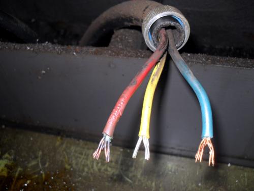
I then set about cleaning up the oil, which gravity takes on a meandering path through the electronics enclosure and the motor bay.  In cleaning up I noticed that phase 1 on the motor feed looked worse for wear.  It has gotten hot and cooked the wire and insulation.  I will have to replace.  Most likely cause is a loose connection.  You can see it clearly here (red wire):
   

I decided to remove the actual mounting board and see if the bolts that hold the feed box on were indeed hiding behind here (I read a post on PM that suggested so but there had been some skepticism).  I can see four lurking in there.  I will need to access these if I need to remove the feedbox

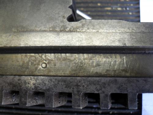
Whilst the paper was soaking up the oil, I decided to remove the jaws on the 3-jaw chuck, as I had been bugging me that someone had put them in out of sequence.  I pulled them out and looked at the numbers stamped onto them.  I had one "6" and two "7" Chin  A few different combinations later and I found which was which.  I then proceeded to stamp them accordingly.
   

I found the manufacturer's badge hiding behind a layer of crap and to me it appears to be the Bison logo.  Although, it doesn't actually say Bison.  I punched "PUTm chuck Poland" into Google and din't get anything of use back.  I wonder if this is early Bison?

     [Image: BISON-FullColor.jpg]

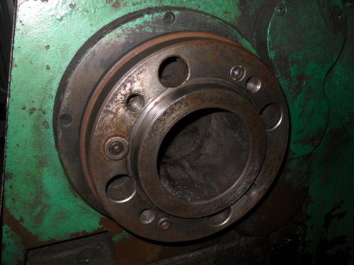
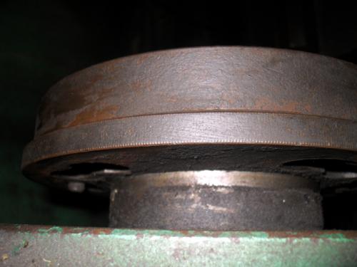
I decided to remove the chuck to check out the DIN55022 mount.  It is pretty straight forward and uses a locking ring that rotates to capture the four studs that extend from the rear of the chuck adapter.  There is a single locating pin and once in place, the four nuts are tightened.  The last pic isn't all that good but it does show the locking ring.
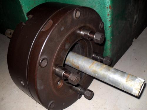


For reference, those are 24mm nuts!
Hunting American dentists since 2015.
Reply
Thanks given by:
#86
That's a cool chuck, and I agree with you that it seems to be an early one that became sold over here as Bison brand. They were very good chucks, fairly close to Pratt-Burnerd in quality. I think they now source them from Asian makers. Sad.

As for the wiring, I assume you'll just replace all of them since you have to pull at least one. They are likely all a bit crispy on the insulation after all the years of sitting in oil and getting warm.
Reply
Thanks given by:
#87
Yes - All will get redone. I should have been more clear. I'll probably replace all the wires, as once I pull the motor wires, I'll probably pull the start/stop ones too.
Hunting American dentists since 2015.
Reply
Thanks given by:
#88
To be honest, I simply haven't had much time to work on the lathe since I got her last year.  One of the things I needed to do was to remove an access plug on the side of the aperon.  I don't have the required 28.5mm hex wrench, so I made one (sort of).  This adaptor allows me to use a 17mm socket to unscrew the plug.


Behind the access plug is the spring loaded worm drive that engages the longitudinal and transverse feeds.  The circular nut that is just visible sets the spring tension.  Apparently, during a crash the spring can disengage but I need to dig into the manual to go over this again.

Someone has slathered everything in grease Bash and it looks like there is grease inside the apron as well.  I think I am going to have to remove the apron.  I'm going to remove the drain plug and see if any oil comes out.  If not, I think I'll fill the apron with kerosene to (hopefully) dissolve the grease.

   
Hunting American dentists since 2015.
Reply
Thanks given by:
#89
Nice work on the wrench/adapter.

Save me from reading back because I'm so lazy (and short on time), are you using the lathe or just tinkering with it when you can?
Reply
Thanks given by: Mayhem
#90
Just tinkering at the moment. My plan however is to migrate my tooling up here. I have decided to make my own tool holders to suit the Dickson tool holder that the lathe has and sell the CA QCTP and holder with the old lathe. I will need some input into the best order and process to make them.

At the moment, it is all a matter of time and money...
Hunting American dentists since 2015.
Reply
Thanks given by:


Users browsing this thread: 1 Guest(s)