Posts: 536
Threads: 39
Joined: Jan 2013
Location: Kelowna, BC, Canada
The following 2 users Like Hawkeye's post:
stevec (02-26-2014), EdK (02-26-2014)
Some years ago, I started to build a tool and cutter grinder, mostly with a view to sharpening endmills. I needed to make a rotary table to mill a curved slot, so I set the grinder project aside. I finished the RT, but never got back to the grinder. This is as far as I got. That's an R8 spindle, since I have a full set of R8 collets.
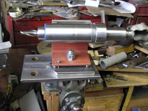
Today, I had a day off so I decided to make the grinder spindle. I figured an MT2 socket would be the most versatile in order to mount whatever I may need to spin as the project grows. I roughed the taper at around 1 1/2*, to be trued up with a tapered reamer.
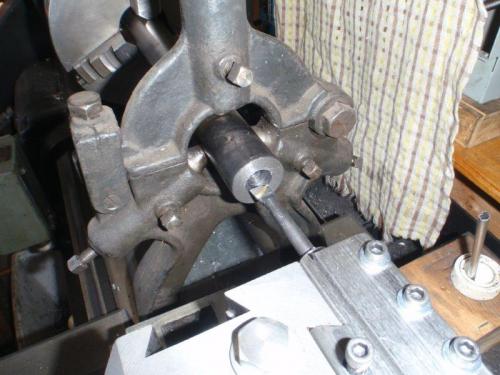
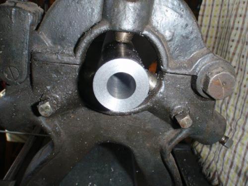
It took quite a while to ream out the MT2 socket, but it came out quite nice.
I got to try out my new swing-up threading tool to cut the pre-loading thread.
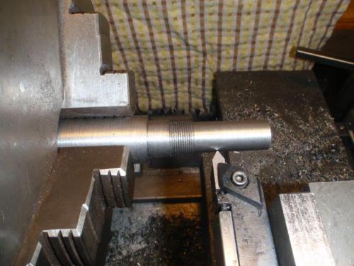
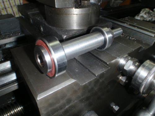
The finished spindle. Next step is the body that the bearings mount in.
Mike
If you can't get one, make one.
Hawkeye, proud to be a member of MetalworkingFun Forum since Jan 2013.
Posts: 2,685
Threads: 29
Joined: Feb 2012
Location: Nova Scotia, Canada
Hawk, Is yours designed after this?
 endmill grinder.jpg
 (Size: 6.72 KB / Downloads: 244)
It's the kind I have. Is your R-8 spindle (the one that holds the endmill, or whatever) going to have compressed air to allow it to "float" and move freely?
Busy Bee 12-36 lathe, Busy Bee Mill drill, Busy Bee 4x6 bandsaw, Homemade 9x17 bandsaw, Ad infinitum.
Posts: 536
Threads: 39
Joined: Jan 2013
Location: Kelowna, BC, Canada
I think I tried to incorporate some of the features of that one, plus some from other sources. I tried injecting air, but it didn't make the spindle move any easier. I haven't seen any plans for an air spindle.
Mike
If you can't get one, make one.
Hawkeye, proud to be a member of MetalworkingFun Forum since Jan 2013.
Posts: 2,685
Threads: 29
Joined: Feb 2012
Location: Nova Scotia, Canada
Experience has led me to believe that if there is enough clearance between the spindle and the bore you end up with play/potential movement that leads to inaccurate grinding. That said it still ads a lot of life to end mills and allows me to reserve my new ones for more precise precision work.
Busy Bee 12-36 lathe, Busy Bee Mill drill, Busy Bee 4x6 bandsaw, Homemade 9x17 bandsaw, Ad infinitum.
Posts: 536
Threads: 39
Joined: Jan 2013
Location: Kelowna, BC, Canada
The following 1 user Likes Hawkeye's post:
EdK (03-09-2014)
03-09-2014, 12:01 AM
(This post was last modified: 03-09-2014, 12:15 AM by Hawkeye.)
I spent some time today making the bearing carrier for the spindle. I really need to get some more tapered-shank drill bits. They are the best way to drill large holes on the lathe.
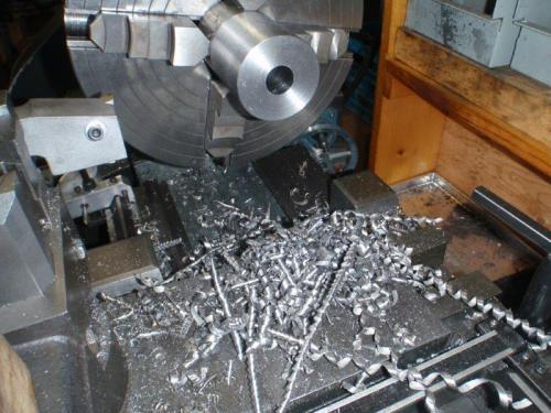
The usual boring work to make the through-hole and the two pockets for the bearings. I managed to sneak up on the pocket diameters for a press fit on both bearings.
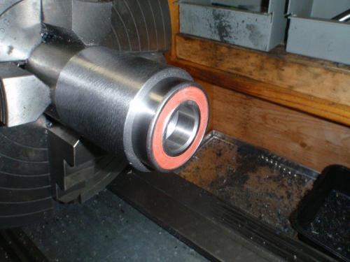
The fit was tight enough that the arbor press wouldn't quite do it, but the hydraulic press had no trouble at all.
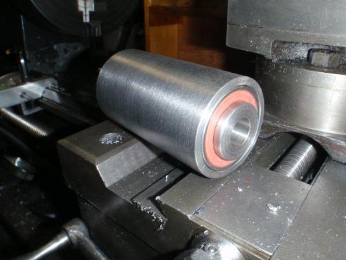
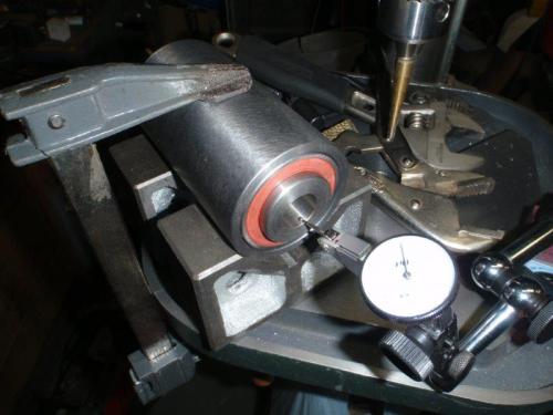
I figured I'd better check the runout, so I set it up as shown. Unfortunately, there is about 0.006" TIR. I'll see what I can do to improve that. It's possible that the economy bearings have some runout.
Mike
If you can't get one, make one.
Hawkeye, proud to be a member of MetalworkingFun Forum since Jan 2013.
Posts: 29
Threads: 4
Joined: Feb 2014
Location: Alabama
That is going to be a nice setup when you get it finished.
Paul
Old Iron`, proud to be a member of MetalworkingFun Forum since Feb 2014.
Posts: 536
Threads: 39
Joined: Jan 2013
Location: Kelowna, BC, Canada
Bummer! I mounted the pulley end of the spindle in the MT3 collet on the lathe, then tried to slide the steady onto the bearing carrier.
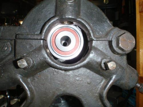
The through-hole is not centred on the lathe spindle.
Plan B. I clamped the carrier to the compound, with appropriate shims. That held it solidly while I touched up the MT2 socket with the tapered reamer.
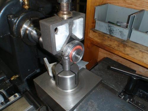
Still reading 0.005" TIR in the test setup, but a ground centre in the socket measures 0.003". It's important to note that this spindle is for the grinding wheel, not for the toolholder. If it's off a couple of thou, it will still work, more like a flycutter. The cup wheel can be trued up, but would have to be repeated each time the wheel is remounted.
Mike
If you can't get one, make one.
Hawkeye, proud to be a member of MetalworkingFun Forum since Jan 2013.
Posts: 2,685
Threads: 29
Joined: Feb 2012
Location: Nova Scotia, Canada
(03-09-2014, 10:05 PM)Hawkeye Wrote: The cup wheel can be trued up, but would have to be repeated each time the wheel is remounted.
I agree and I doubt if a wheel could be remounted without needing to be trued even if the spindle was dead nuts on. 
Busy Bee 12-36 lathe, Busy Bee Mill drill, Busy Bee 4x6 bandsaw, Homemade 9x17 bandsaw, Ad infinitum.
Posts: 536
Threads: 39
Joined: Jan 2013
Location: Kelowna, BC, Canada
That's pretty much what I was thinking.
Mike
If you can't get one, make one.
Hawkeye, proud to be a member of MetalworkingFun Forum since Jan 2013.
Posts: 2,328
Threads: 271
Joined: Jun 2014
Location: La Libertad, Philippines
(03-10-2014, 06:13 AM)stevec Wrote: (03-09-2014, 10:05 PM)Hawkeye Wrote: The cup wheel can be trued up, but would have to be repeated each time the wheel is remounted.
I agree and I doubt if a wheel could be remounted without needing to be trued even if the spindle was dead nuts on. 
There's enough clearance between the hub of the wheel and the spindle nose to necessitate redressing after each mounting of the wheel. Its a trade practice on grinders in general. I even true up my pedestal grinder wheels with a diamond dresser. Makes for easier and better HSS tool sharpening.
|


