Posts: 4,683
Threads: 93
Joined: Feb 2012
Location: Perth, Australia
The following 1 user Likes Mayhem's post:
oldgoaly (08-14-2013)
10-18-2012, 09:02 PM
(This post was last modified: 10-20-2012, 11:37 PM by Mayhem.)
Hunting American dentists since 2015.
Posts: 4,683
Threads: 93
Joined: Feb 2012
Location: Perth, Australia
The following 1 user Likes Mayhem's post:
oldgoaly (08-14-2013)
10-18-2012, 09:27 PM
(This post was last modified: 10-20-2012, 11:37 PM by Mayhem.)
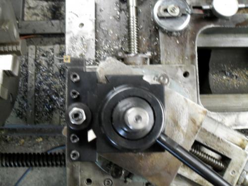
The tool post was a 4 position turret, which meant shimming everything, which I soon decided wasnt a lot of fun.
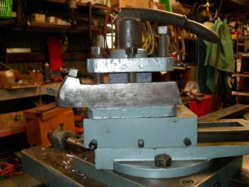
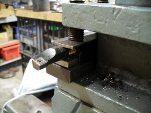
I did manage to pick up some old tool holders for 1/2" HSS blanks and also a HSS cut off tool and an Armstrong threading tool.
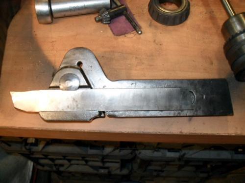
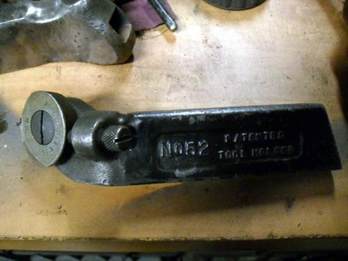
Whilst this did cut down on the shimming, the tool post was still cumbersome to use.
Once I knew the lathe was functional, I made the decision to buy a QCTP. It was suggested to me (by PixMan) that I get a CA size import from Jeff Beck at tools4cheap. So, I contact Jeff and ordered one ($300) and Jeff kindly spread the tool post and holders over 3 USPS flat rate postage boxes ($50 per box). So, for $450 I got a QCTP that would have cost me 3x the price to buy here!
Not long after I got the QCTP I was in the US for a meeting and had the opportunity to meet up with PixMan. We spent some time in his Dads shop and made a 7/8-14 stud to fit the QCTP, which I could finish off when I got home.
That was only the second time I had cut a thread on a lathe and it was quite nerve racking having to do it on a lathe where all the controls were different and someone with a bucket load of experience was peering over my shoulder. I was actually more nervous about crashing his lathe than I was about cutting the thread. However, he is a great teacher and it all worked out in the end. You will note from the pictures that the toolpost stud mounts quite differently on my lathe to most.
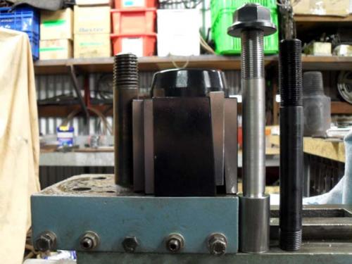
Here is a picture of the QCTP sitting on my compound and (from Left to Right) the original 1-1/4" stud (in situ), the newly turned stud and the stud that came with the QCTP.
Close up of the thread
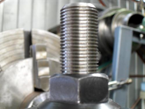
The thread was cut using a 14 pitch lay-down threading insert. Unfortunately, I cannot remember the exact insert used but Im sure PixMan can enlighten us. We picked up two from Hemley Tool Supply in CT on our way from NY to MA (I guess he was also nervous about me crashing things!). In the end, the thread cut beautifully (as you can see) and the insert still looked brand new when we finished.
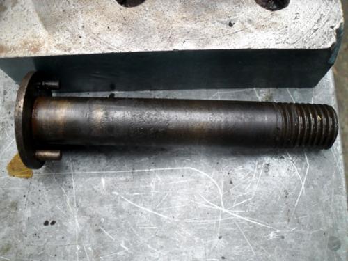
Once I got home, it was time to finish of the stud. As you will see, the stud on my lathe doesn't slide in a T-slot. Nor does it simply screw into the compound. Instead, my stud is a press fit.
Here is the top of the compound with the original turret removed, showing the 1-1/4" stud in place
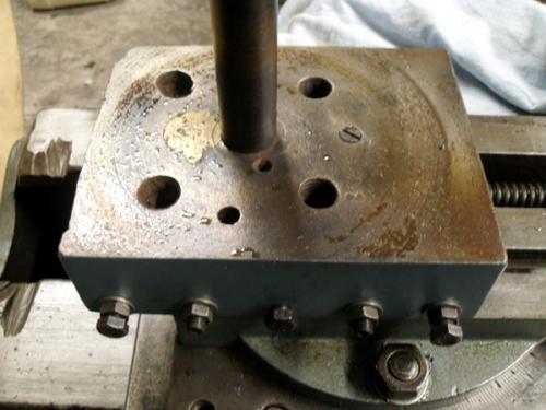
Stud pressed out. Note the locating pins on the flange
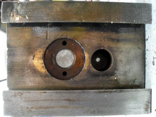
Underside of compound, showing the recess for the stud flange and the two locating holes
Hub ready to be welded onto the stud
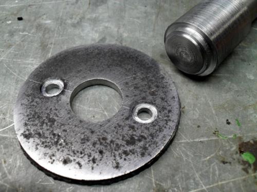
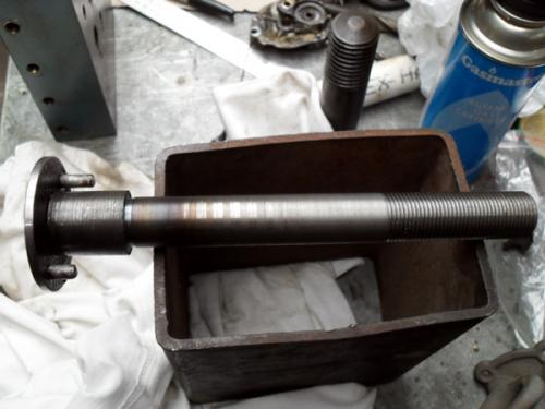
Finished product
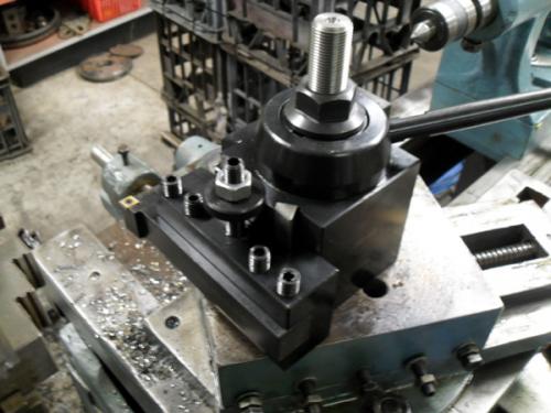
All set up and ready to rock!
Hunting American dentists since 2015.
Posts: 4,683
Threads: 93
Joined: Feb 2012
Location: Perth, Australia
The following 1 user Likes Mayhem's post:
oldgoaly (08-14-2013)
10-18-2012, 10:05 PM
(This post was last modified: 10-20-2012, 11:38 PM by Mayhem.)
I actually missed one post, which should have preceded the one on the QCTP. 
Once the lathe was operational I attacked scraps of metal and slowly tightened gibs and made adjustments that needed to be made. The compound slide only has three adjustment screws and if you want to work close to the chuck you often have one of these hanging out in the breeze. So I decided it would be worth adding a couple extra screws.
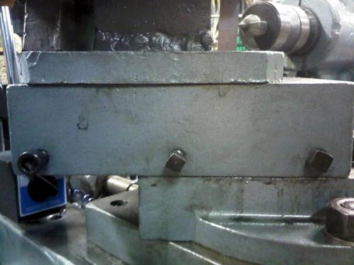
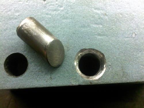
One of the holes had stripped, so I decided to drill them all out to 1/2" and braze in some steel plugs, which I would then drill and tap for the original 7/16" bolts. The top of the pins were bevelled, as was the mouth of the hole (I actually went a little more aggressive on the metal removal that these pics show).
Plug and hole prepared
All plugs brazed into place and drilled for tapping
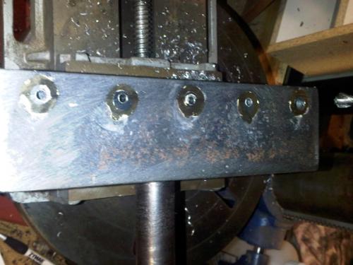
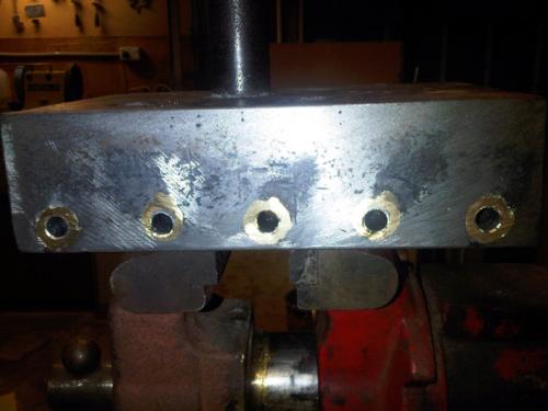
A mismatch of bolts but all done!
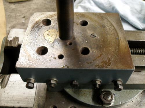
The centre one doubles as a lock. I drilled a hole through this bolt and pushed some nylon line trimmer cord through this hole and then trimmed it flush to the major diameter. This is the male version of a Nylock nut and will not rattle loose.
Just out of interest - here is a picture of the compound nut, which is cast iron.
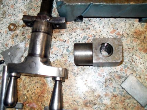
At the same time I also removed the cross slide screw, as it was bent. I didn't notice this before, as the front retaining housing was also loose and masked the bend. The issue was in the front portion of the screw and given the damage to the handwheel, I'm guessing someone clipped it with a forklift. I pressed almost all of the bend out and it is much better now.
The bend is slight but annoying when cranking the handle
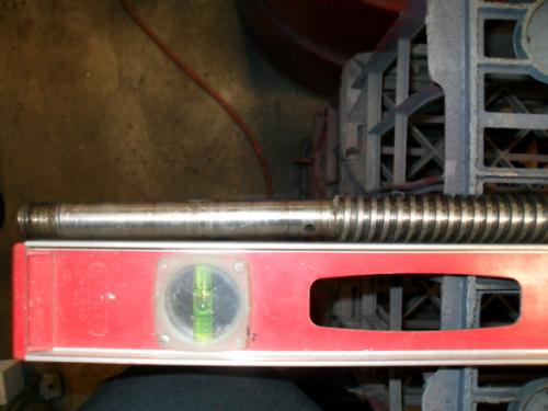
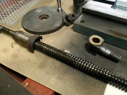
Here is the nut (still on the), screw, front bush and handwheel.
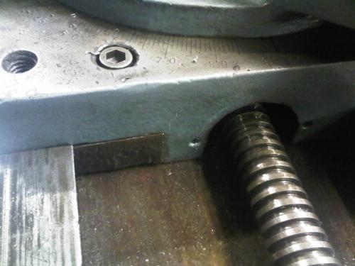
Here is the front gib adjustment screw on the cross slide.
There was always some play in the cross slide which was more than just backlash. I finally figured out that the hole visible in the shaft (where it is sitting on top of the level) is for a pin, which retains the thrust bearing. Once I place a washer and pin in place the cross slide behaved much better.
Hunting American dentists since 2015.
Posts: 4,683
Threads: 93
Joined: Feb 2012
Location: Perth, Australia
The following 1 user Likes Mayhem's post:
oldgoaly (08-14-2013)
10-18-2012, 10:44 PM
(This post was last modified: 10-20-2012, 11:38 PM by Mayhem.)
You may recall that I mentioned that I met someone from the far North of Western Australia, who has a similar lathe. Well he was kind enough to not only send me pictures of his lathe (and specifically the parts on mine that are missing) but he also dismantled some of it, so I could better understand how it works.
A few pics of his lathe:
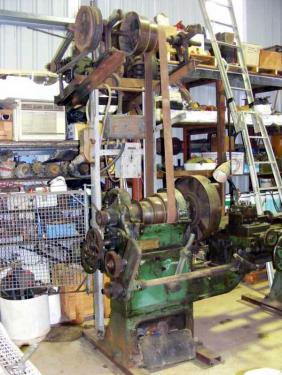
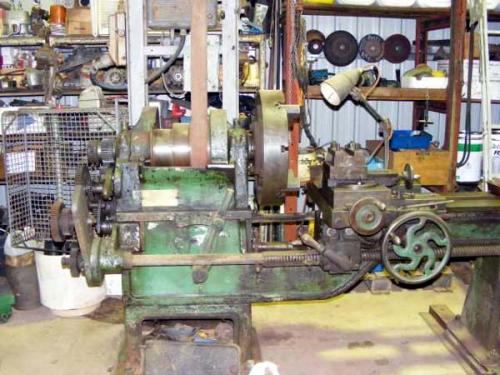
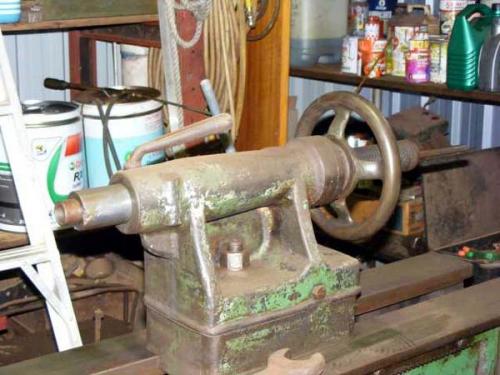
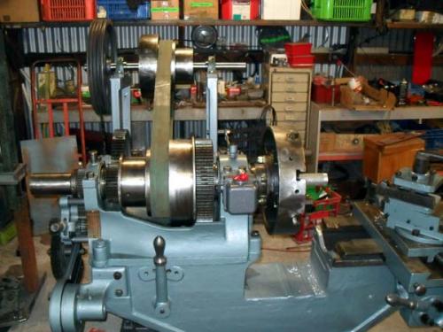
On these lathes, the feed is driven from a shaft that runs on the rear of the lathe. This shaft is chain driven off of the tumbler output.
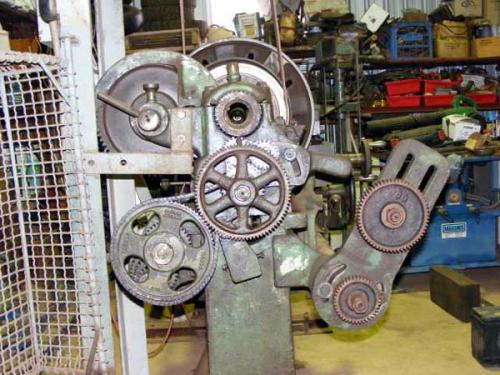
In the picture above, it actually looks like the change gear is meshed with the driven sprocket. However, the two do not line up and there is no interference, as you will see below:
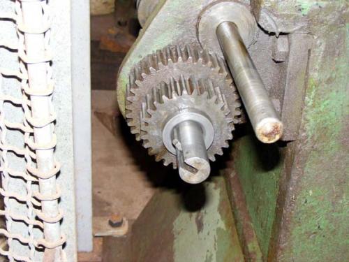
The chain drives a three gear cluster, which mates with three independent gears on the feed shaft.
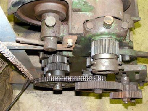
The gear cluster/independent gears viewed from behind
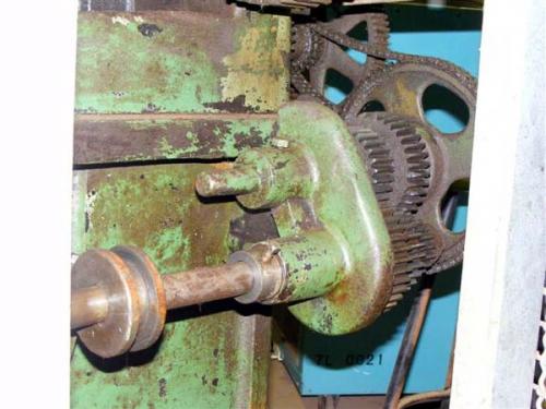
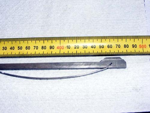
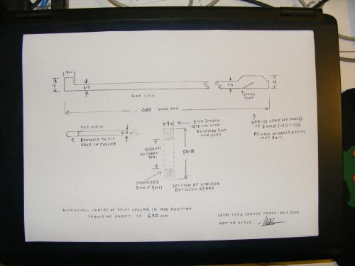
The large lever on the front of the headstock (visible in the second pic in this post) moves a collar, which in turn, moves a spring loaded key. There is a bevelled spacer between each of the independent feed shaft gears, which pushes the key down, allowing it to slide from one gear to the next. So, the five detent positions on the lever correspond to High / Neutral / Medium / Neutral / Low.
The feed rate change lever on my lathe
The cluster removed from its shaft and one of the independent gears removed to show the bevelled spacer and the key
The spring loaded key and one of the bevelled spacers
 Old lathe2 001.jpg
 (Size: 30.25 KB / Downloads: 247)
Close up of the spring
The technical stuff (Ed will probably replicate this in CAD)
Hunting American dentists since 2015.
Posts: 4,683
Threads: 93
Joined: Feb 2012
Location: Perth, Australia
The following 1 user Likes Mayhem's post:
oldgoaly (08-14-2013)
10-18-2012, 11:13 PM
(This post was last modified: 10-20-2012, 11:39 PM by Mayhem.)
Our lathes differ in relation the chain drive; with mine looking like it originally had a lay shaft (based upon the tumbler bracket and the length of the shaft for the gear cluster.
Chain sprocket on tumbler output
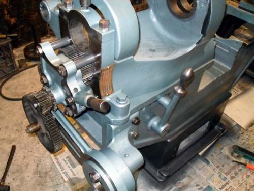
Here you can the vacant hole in the bottom LH corner of the bracket. The gear cluster, the feed bracket and the selector are visible as well
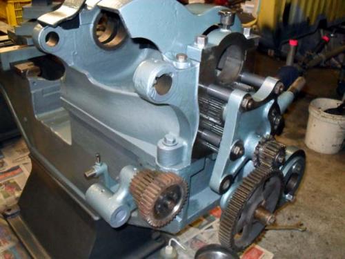
Note on his lathe, the tumbler gears are open (you can see this in the 4th and 5th pictures in the previous post.
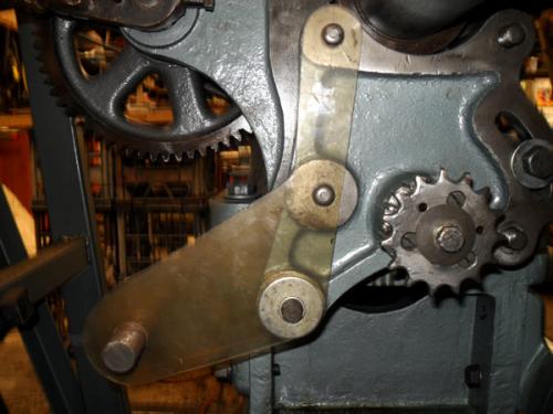
Rather than mess around with a lay shaft, which meant another set of sprockets and chain, I decided it would be simpler to extend the cluster gear shaft to accommodate the chain sprocket and align it with the chain sprocket on the tumbler. To do this I needed to make up two brackets that would straddle the tumbler bracket and support the (new) longer drive shaft. I mocked these up using cardboard, then Perspex and finally I cut them from 3mm plate.
Perspex mock up
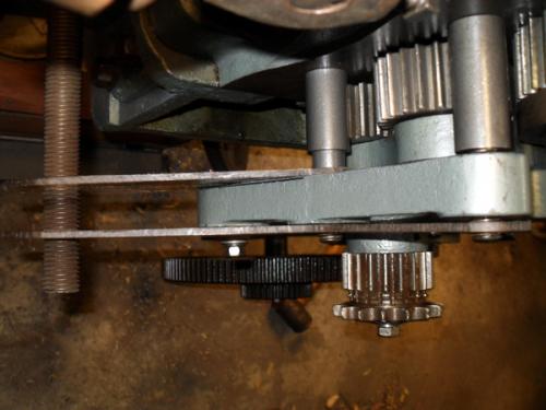
Top view (1" stud filling in as an extended shaft!)
Using such a large bolt seemed silly, so I turned a plug to accommodate a 3/8-16 bolt
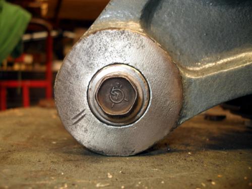
A couple of bronze top hats and the 1 shaft is now supported and ready to have the gear cluster and chain sprocket fitted.
Final brackets finished and in position
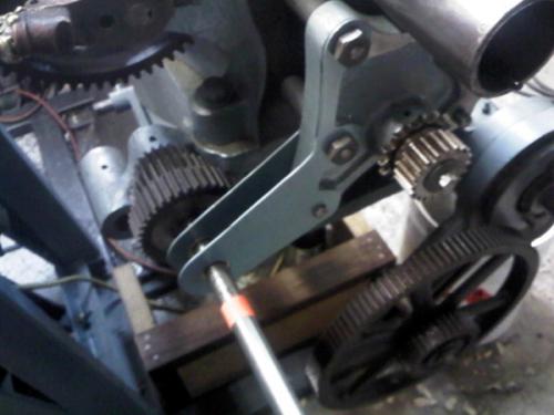
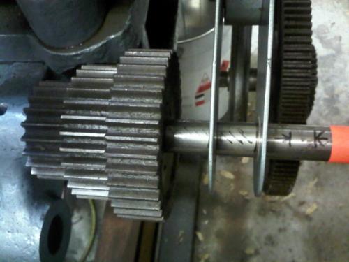
As the shaft will now turn (in the original design the gear cluster rotated on the shaft), a bronze bush will be turned up and inserted into the housing in which it resides, along with a thrust bearing.
The other lathe has a 21t sprocket driving a 76t sprocket, giving it a drive ratio of 3.62:1. The sprocket I have on my tumbler has 15 teeth and the closest off the shelf sprocket I could find to match the aforementioned ratio has 54 teeth. This will give me a drive ration of 3.6:1, so I'm happy with that.
Hunting American dentists since 2015.
Posts: 4,683
Threads: 93
Joined: Feb 2012
Location: Perth, Australia
The following 1 user Likes Mayhem's post:
oldgoaly (08-14-2013)
10-19-2012, 12:54 AM
(This post was last modified: 10-20-2012, 11:40 PM by Mayhem.)
Hunting American dentists since 2015.
Posts: 4,683
Threads: 93
Joined: Feb 2012
Location: Perth, Australia
The following 1 user Likes Mayhem's post:
oldgoaly (08-14-2013)
10-19-2012, 01:18 AM
(This post was last modified: 10-20-2012, 11:41 PM by Mayhem.)
Hunting American dentists since 2015.
Posts: 825
Threads: 25
Joined: Jul 2012
Location: N. Bay Ontario
The following 1 user Likes sasquatch's post:
oldgoaly (08-14-2013)
Mayhem,, An excellent presentation of the lathe rebuild.
Very enjoyable and interesting to follow this large project.
Nicely done, and much appreciated for posting this.
sasquatch, proud to be a member of MetalworkingFun since Jul 2012.
Posts: 4,463
Threads: 184
Joined: Feb 2012
Location: Missouri, USA
Indeed.
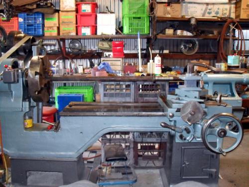
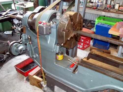
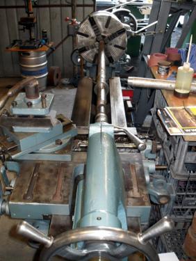
That is quite a machine, and an excellent job of restoring that lathe.
If it were not for all the great pictures I would have said it never happened, so now I guess I have to believe you Darren.   
No doubt about it - you don't have any excuses for not knowing that lathe inside and out now. 
Thanks for taking the time to put all that together too. An excellent post Sir! 
Willie
Posts: 8,863
Threads: 319
Joined: Feb 2012
Location: Arizona/Minnesota
Excellent thread Darren!
That looks like a very nice and heavy duty lathe that should do the job for you. I like the color you chose for painting the lathe. 
Ed
|
