Posts: 2,344
Threads: 53
Joined: Feb 2012
Location: Spencer MA USA
The following 1 user Likes PixMan's post:
Mayhem (11-09-2014)
Thanks for posting about it, I was going to ask if you'd had any progress.
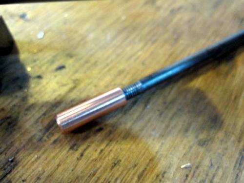
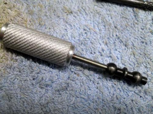
Not sure what I'm looking at in the second photo, but I believe it's the screw in the first photo as installed. Why would you have to turn off the projection at the end of the screw? Doesn't it serve some purpose? Just what does that screw do?
That flame cut (or poorly laser cut?) part looks like something we could have made. Was the original missing? I do hope all the hand fitting of parts makes for a good, smooth running assembly. Judging from some of the engineering (or lack thereof) that I've seen with that machine, it's simply GOT TO be better than what the Kondia factory originally shipped!
BTW, which photos would you like me to send you or post?
Posts: 4,683
Threads: 93
Joined: Feb 2012
Location: Perth, Australia
Thanks Ken.
Yes - I was going to put an arrow to point to the screw in Photoshop but then I forgot. I thought that the projection was to keep the reverse trip ball lever level but the hole in the lever is too small. I looked online and saw that the corresponding part on the Bridgeport's ( N° 69) do not have the projection. As the screw goes in crooked, I had to face a little off the end, otherwise it bit into the plunger and prevented the plunger and the micrometer screw from moving. Honestly, I think the screw is simply there to keep crap from getting into the hole.
The poorly feed trip lever was a new part from Kondia, as the original one was missing. There are a number of parts that I could have made if I had the original part for comparison. However, so much was missing that I couldn't do anything but order new. There were exceptions like handles and fasteners etc.
The pics I was referring to were those we took when repairing the worm feed shaft.
Hunting American dentists since 2015.
Posts: 4,683
Threads: 93
Joined: Feb 2012
Location: Perth, Australia
The following 1 user Likes Mayhem's post:
PixMan (11-16-2014)
Well I lost half a day yesterday trying to sort out computer issues, so I didn't get as much done as I had hoped. I also didn't takes as many pictures as I should have, so you will have to use your imagination with some of my descriptions! Having said that, I seem to have to strip down the work I have done quite frequently to sort out other issues, so there may well be more pics!
First off, I am going to post some pictures of the work Ken and I did on some parts when I visited him last month. You have seen the issues with these parts and have seen the finished parts in previous posts. What was missing however, was the actual repair:
The first one is very simple. Kondia shipped me a part that was missing a hole. The part was the micrometer screw, which allows the quill travel to be stopped at a specific point. It also trips the quill feed. Kondia sent me the drawing, which showed the hole at a specified distance from the end of the screw, parallel to the slot in the other end. It also specified the diameter and tolerance of the hole. Now this is a very simple job, which I could have done if my mill was up and running. However, it wasn't something I was going to attempt on my drill press. Also, the 6.5mm reamer I needed was waiting for me in the US.
Set up to ensure the hole is parallel tot he slots, as specified on the drawing.

Finished.
 20141027-007.JPG
 (Size: 13.44 KB / Downloads: 104)
The next job was a little more tricky, as the hole in the feed shaft had been drilled off centre and at an angle. The new hand wheel coupling also had a hole that was drilled at an angle (although very slight). The main issue was the the detent ball wouldn't work and in fact locked the selector shaft from moving.
Ken and I discussed options and both agreed that the best approach was to weld up the hole in the shaft and drill a new one. Before we could weld it, we needed to turn up a slug of copper that would slide inside the shaft to prevent the weld penetrating into the bore. We then headed over to see Jen (Allessence), who very kindly welded up the hole. Once cool it needed a little persuasion to straighten the shaft and to pull out the slug. I ran a 7mm reamer through the bore and there was no resistance. We lined up the collar, marked with a transfer punch and put the hole where it should be and drilled, reamed and countersunk the hole. We then reamed the bore again and after some fiddling with fitting, the whole assemble worked as it should.
I scribed the position of the hole in the coupling in relation to the shaft. I've coloured this in photoshop so it is easier to see.

The copper plug and retrieval tool.

Hole welded and cleaned up.

New hole

Finished assembly

Hunting American dentists since 2015.
Posts: 4,683
Threads: 93
Joined: Feb 2012
Location: Perth, Australia
The following 4 users Like Mayhem's post:
PixMan (11-16-2014), DaveH (11-16-2014), EdK (11-16-2014), Highpower (11-17-2014)
Last week I was trying to get the very roughly machined feed trip lever (FTL) to fit and function. One of the problems I found is that the hole drilled into the head where the reverse trip ball lever (RTBL) inserts is not accurate. So, although the drawing for the micrometer screw gives the position of the hole, its location in relation to the slot into which the FTL sits is not parallel.
Ken noted that the drawing indicates "at assembly" for the hole and we did wonder about the consequences of drilling based upon the drawing. My concern was the position of the hole in relation to the length of the screw, given the travel of the screw trips the lever. The solution was to thin the FTL to allow rotation of the screw so that the RTBL would seat and function.
Given the need to pull the RTBL out and put it back in several times whilst filing the FTL, I made a special tool.

Something tells me that I am going to need this again. Besides, I can never find a M3 screw when I need one...
The next task was to get the trip handle to actuate the cam rod. I started by grinding the tip down and trying. After several cycles, I noticed that the shoulders (where they had milled the flats that sit into the feed trip bracket) were rubbing on the feed trip bracket. I extended these flats further down the trip handle with a hacksaw and a file. The result was a fully functional lever that was a bit loose. So, I welded a bit back onto the top and rounded it off. It now feels better. Sorry, no pictures.
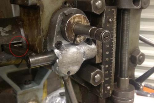
With this done, it was time to attach the overload clutch trip lever to the overload clutch and fit this. The drawing (see below) shows a plunger and spring (A). However, there was no corresponding hole in the head at this position. There was one at position B and given that the spring and plunger was missing, I have no Idea where they were.

I looked at a picture from another Kondia that someone sent me and you can see the steel plunger where the drawing shows it to be.

You can see on my mill that there is no hole that corresponds with the drawing.


Hole B actually lines up with a notch on the arm, so I went ahead an used this.

It all seems to work as it should, although I have to read up on setting the tensions etc.
Actuated.

Tripped.

I have read that these early Kondia mills required a lot of "at assembly" work to get them functional, so I expected that a lot of parts simply wouldn't bolt straight on. Whilst it is a long slow process, I am really enjoying the challenges and I'll know this thing inside out one I am finished.
Hunting American dentists since 2015.
Posts: 2,344
Threads: 53
Joined: Feb 2012
Location: Spencer MA USA
The following 1 user Likes PixMan's post:
wrustle (11-19-2014)
Wow, that's fantastic progress! I don't know if I'd ever have the patience to fiddle around with the assembly for so many total hours, so kudos to you.
I'm so happy to see the parts we worked on now in the machine and being used. I continue to find it almost amusing just how "one off" your machine seems to be. Even Bridgeport had a lot of evolutionary engineering changes, but your machine doesn't seem to have any traceability back to the maker. That you are able to figure it out and make it work is testament to your mechanical abilities and especially...determination to get it working PERFECT!
Good job!
Posts: 4,683
Threads: 93
Joined: Feb 2012
Location: Perth, Australia
Thanks Ken - I really appreciate your comments. I wouldn't be even half way to where I am now without your help.
Hunting American dentists since 2015.
Posts: 4,513
Threads: 139
Joined: Feb 2012
Location: Kempton Park. South Africa
Magic job Darren 

DaveH
Posts: 3,003
Threads: 51
Joined: Apr 2012
Location: Ontario
Great reverse engineering Darren. Not sure I'd have the patience. Hard to believe they could produce machinery in a factory setting that didn't fit the drawings. Its one thing for us to build a one of and make changes along the way but not on a line. Could you imagine taking a vehicle in for service and a mechanic having to hand fit the parts.
Free advice is worth exactly what you payed for it.
Greg
Posts: 2,344
Threads: 53
Joined: Feb 2012
Location: Spencer MA USA
(11-16-2014, 08:59 AM)Mayhem Wrote: Thanks Ken - I really appreciate your comments. I wouldn't be even half way to where I am now without your help.
Darren,
I'm just so happy to be able to help in some small way, despite the distance. Given the cost of machines there, I would think that once done and running you would still have a top condition machine that you would otherwise be unable to find or buy there regardless of the money you've had to spend on parts from Kondia. It will serve you well for a great many years, and who knows, perhaps in the coming years you might switch to ball screws and add a CNC control.
Cheers!
Ken
Posts: 4,683
Threads: 93
Joined: Feb 2012
Location: Perth, Australia
The following 1 user Likes Mayhem's post:
PixMan (11-17-2014)
Thanks Greg,
From what I understand and what I can tell, most of the mill matches the drawings that I have, with a few noticeable exceptions. The main issues appear to be holes that have been drilled with minimal accuracy. I sometimes wonder if Manual worked for Kondia before heading the Torquay and entering the services of Basil Fawlty... As such, several parts have been shipped new from Kondia incomplete.
I'm unsure of how many were finished like this, or even how many were built in one production run. I certainly know that some of the parts were revised after my mill was built, as evidenced by the drawing for the feed trip bracket.
Thanks Ken,
You are certainly correct regarding the price. Even with the parts that I had to buy from Kondia (approx US $1K) and other materials I have had to buy, this mill will finish up costing the same, if not less than the cheapest second hand mill I have seen advertised in several years. The other advantage is that I can invest money into it when I can afford to, rather than dropping 4K and then figuring out how to move it and then find out what its issues really are... I had considered ball screwsbut of the companies in the US I contacted for a price, none bothered to answer my emails.
Your help and advise, and that of others here, has been invaluable in solving problems, and actually getting parts made or fixed.
Hunting American dentists since 2015.
|


