Henry,
I am no great fountain of knowledge about DRO's, but I do have a fair number of years in using them (about 30 at last count), and you follow my recommendations only if you want to.
Having DRO's on your lathe (or mill) isn't the be all and end all to getting accurate machining done, as some people seem to think, you have to fine tune your lathe (or mill) to be able to use them correctly, and in your situation, it could mean a lot of strip downs of your setup. I am lucky in that I have tapered gibs, so I can tweak them without resorting to strip downs.
When you first come to use them in anger, you will most probably find that when you put on a decent cut, your tooling will get 'kicked back' by the cutting pressure, and your DRO will show that, and you will start chasing your own tail trying to get a cut to stay on accurately.
You have to balance the gib pressure enough to stop that throw off without making the handles too hard to turn, or maybe do the mod that I showed on locking up the cross slide and use that to balance the pressures out.
Forget about backlash in your leadscrews etc, your DRO's are giving you absolute measurement of where the the tool tip is, and you have to train yourself to respect and trust your DRO set up, otherwise it was useless fitting it in the first place.
You cannot beat experience in finding what is best for your type of machining requirements, so stick with it and you will soon get used to it.
Get that sorted now, and you should end up with a well balanced system that will give you years of accurate and trouble free service. In fact, my mill hasn't had anything touched now for well over 3 years, and the lathe, a couple of years (I had to take the cross slide off to do a little job). My DRO's stay rock solid (within a couple of tenths anyway) all the time, no matter how much cut I put on.
John
Well said John. Extremely good advice. The first time I used one in a job shop I was chasing my tail for a while till an old timer gave me that same advice.
"Billy G"
Posts: 170
Threads: 9
Joined: Apr 2012
Location: Southern California
(07-06-2012, 01:23 AM)Bogstandard Wrote: Henry,
I am no great fountain of knowledge about DRO's, but I do have a fair number of years in using them (about 30 at last count), and you follow my recommendations only if you want to.
Having DRO's on your lathe (or mill) isn't the be all and end all to getting accurate machining done, as some people seem to think, you have to fine tune your lathe (or mill) to be able to use them correctly, and in your situation, it could mean a lot of strip downs of your setup. I am lucky in that I have tapered gibs, so I can tweak them without resorting to strip downs.
When you first come to use them in anger, you will most probably find that when you put on a decent cut, your tooling will get 'kicked back' by the cutting pressure, and your DRO will show that, and you will start chasing your own tail trying to get a cut to stay on accurately.
You have to balance the gib pressure enough to stop that throw off without making the handles too hard to turn, or maybe do the mod that I showed on locking up the cross slide and use that to balance the pressures out.
Forget about backlash in your leadscrews etc, your DRO's are giving you absolute measurement of where the the tool tip is, and you have to train yourself to respect and trust your DRO set up, otherwise it was useless fitting it in the first place.
You cannot beat experience in finding what is best for your type of machining requirements, so stick with it and you will soon get used to it.
Get that sorted now, and you should end up with a well balanced system that will give you years of accurate and trouble free service. In fact, my mill hasn't had anything touched now for well over 3 years, and the lathe, a couple of years (I had to take the cross slide off to do a little job). My DRO's stay rock solid (within a couple of tenths anyway) all the time, no matter how much cut I put on.
John
John, Thanks for the advice. I am an amateur and I'm always willing to listen to advice. I have had a 3 axis DRO on my mill for 3 years and it is fantastic. I'm confident that with practice, I will improve the accuracy of the work I do on my lathe.
Henry Arnold
henryarnold, proud to be a member of MetalworkingFun Forum since Apr 2012.
Posts: 170
Threads: 9
Joined: Apr 2012
Location: Southern California
07-06-2012, 01:29 PM
(This post was last modified: 07-07-2012, 10:11 AM by henryarnold.)
Today I installed the X Axis Scale. You might be wondering how I have so much time to work on this project. I'm on vacation this week. Last week I finished off my wife's list of things to do around the house and so this week I am able to knock off this DRO project.
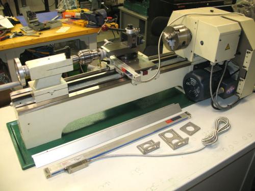
Here are the parts for the X Axis installation. The scale, the cover, and the brackets.
I was concerned about how parallel the end of the carriage was with the face of the bed so I used a digital level. I set it to zero on the top of the cross slide.
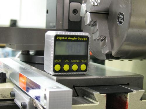
The end of the carriage read 89.0 degrees. I would have expected 90.0 degrees but as it turns out the bed is off by almost the same amount.
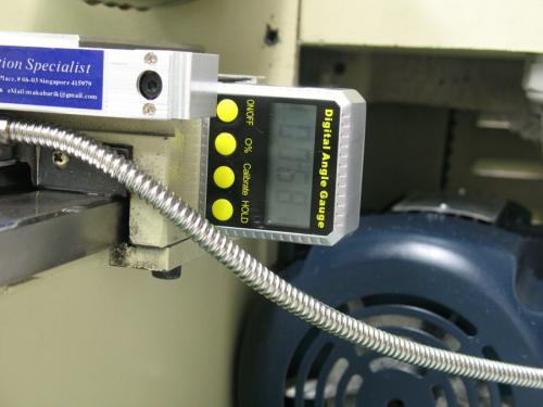
Here's the reading off the bed which is 88.1 degrees. I wasn't sure what to do about the 0.9 degrees difference but as the installation progressed, it seems that this amount was not a problem.
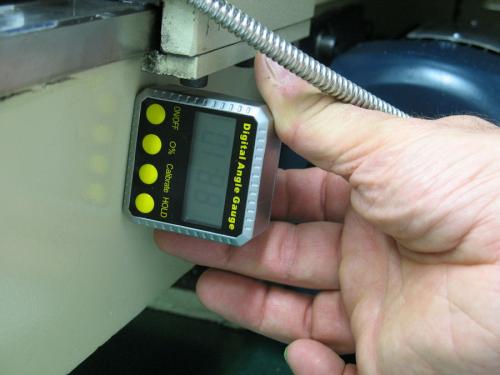
You'll notice that it looks like the level is at an angle that is not even close to 90 degrees. This is an allusion caused by the camera angle. Remember this later when it looks like I'm drilling and tapping what appear to be crooked holes. 
henryarnold, proud to be a member of MetalworkingFun Forum since Apr 2012.
Posts: 170
Threads: 9
Joined: Apr 2012
Location: Southern California
07-06-2012, 01:44 PM
(This post was last modified: 07-06-2012, 01:57 PM by henryarnold.)
The placement of the scale is critical to making sure that the carriage can be move through it's full travel. It's also important that the height of the scale match the reach of the bracket that connects to the pickup and the back of the carriage. I used two powerful magnets to temporarily mount the scale to the bed so I could move it around for the best position.
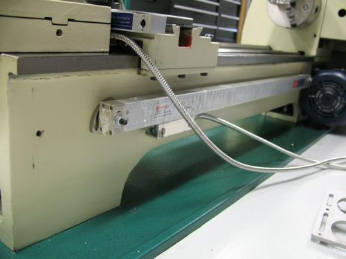
The bracket is aluminum so I used double sided tape to mount it temporarily so that I could check where it would line up with the scale pickup. Once I got everything in a position that worked, I made small ink pen marks on the lathe and removed the scale and bracket.
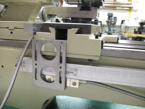
I then measured the placement of the bracket holes on the carriage and the scale mounting holes on the bed.
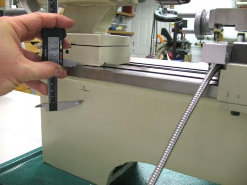
I center punched each location and then rechecked the dimensions. The bracket holes are 60 mm apart and for my scale the mounting holes are 700 mm apart. I don't have any accurate tool to mark off 700 mm so I used an aluminum yardstick and eye balled it the best I could.
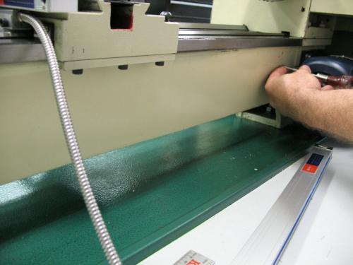
henryarnold, proud to be a member of MetalworkingFun Forum since Apr 2012.
Posts: 170
Threads: 9
Joined: Apr 2012
Location: Southern California
07-06-2012, 02:02 PM
(This post was last modified: 07-06-2012, 02:04 PM by henryarnold.)
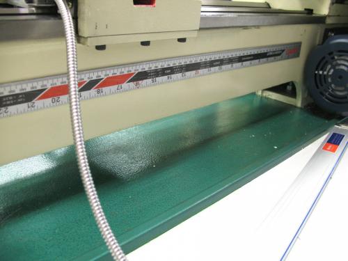
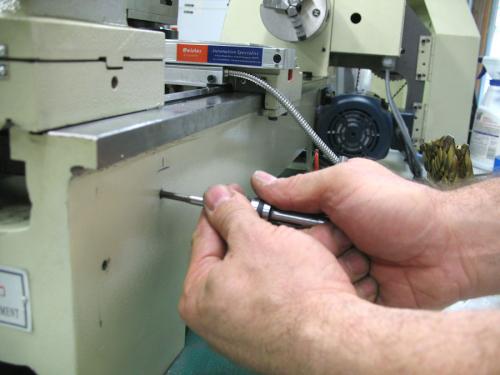
These photos look like I drilled and taped my holes at an angle. The camera angle makes it look like that. I checked each hole with a square as I was drilling it. All of the screws used were 5 mm screws so I drilled 5 mm holes in 4 places.
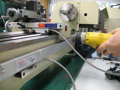
I tapped first with a taper tap and then with a bottoming tap
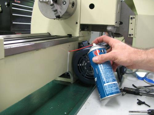
One of my tricks for cleaning out a blind hole hole is to flood it with WD-40 or similar lubricant which flushes out that nasty cast iron powder.
henryarnold, proud to be a member of MetalworkingFun Forum since Apr 2012.
Posts: 170
Threads: 9
Joined: Apr 2012
Location: Southern California
07-06-2012, 02:06 PM
(This post was last modified: 07-06-2012, 02:19 PM by henryarnold.)
With all the holes drilled, I mounted the scale and loosely mounted the bracket. The bracket is is screwed to the bottom of the pickup with two 4 mm screws. There is a plastic protector on the scale pickup that is not removed until everything is aligned.
I adjusted the planarity of the scale using a dial gage on the carriage. This adjustment needs to be within 0.007" over the length of the scale. The bracket screws are still loose at this point.
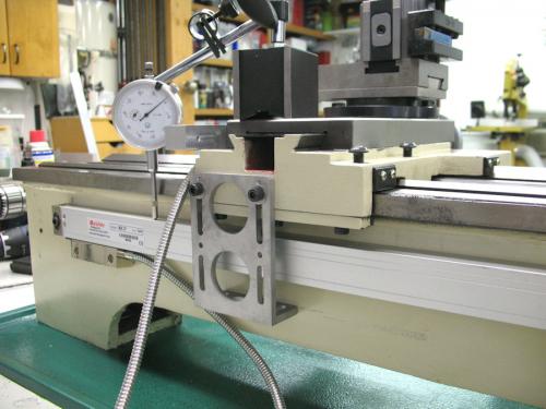
Using 3 feeler gages that total 0.055", I adjusted the clearance of the pickup to the scale body. The plastic protector is removed before making this adjustment. Tightening the bracket screws locks in the pickup clearance.
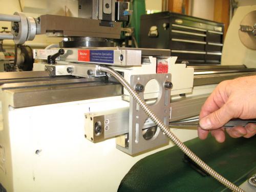
I hooked up the display and my new X scale worked fine so I wire tied the cables so that they don't strain the cable at the entry point to the pickups.
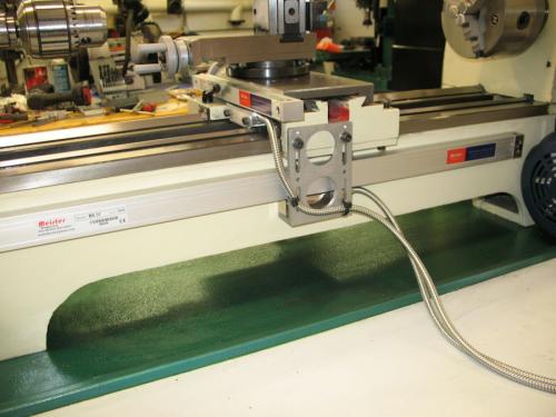
Last photo before putting the splash guard back in place.
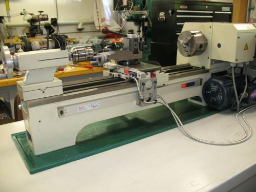
All done except for mounting the display
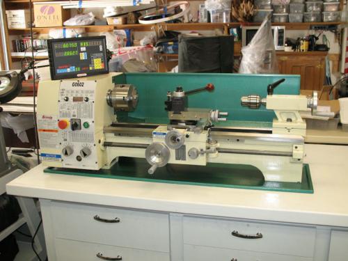
You'll notice that I haven't installed either of my scale guards. I'm still thinking about whether I really need to but I will show you how they are installed later if I install them.
The last thing I need to do is fabricate a mounting post for the display.
henryarnold, proud to be a member of MetalworkingFun Forum since Apr 2012.
Posts: 3,003
Threads: 51
Joined: Apr 2012
Location: Ontario
The angles your reading will be the draft on the patterns, needed to get them out of the sand mould.
Free advice is worth exactly what you payed for it.
Greg
Posts: 170
Threads: 9
Joined: Apr 2012
Location: Southern California
07-07-2012, 01:38 AM
(This post was last modified: 07-07-2012, 01:39 AM by henryarnold.)
(07-06-2012, 02:33 PM)f350ca Wrote: The angles your reading will be the draft on the patterns, needed to get them out of the sand mould.
Thanks for the explanation. I wasn't saying that the side of the lathe bed should be square. I knew it would not be. My concern is to make sure that the bracket mount and the pickup are parallel to each other which is why I was checking the angles. In a worst case scenario, if your lathe had greatly sloping sides to the bed, the bracket that connects to the carriage would have to compensate for the angle. On my mill I had a situation where I had to make a small block with an angled face to allow the scale pickup to be square to the body of the scale.
henryarnold, proud to be a member of MetalworkingFun Forum since Apr 2012.
Posts: 4,513
Threads: 139
Joined: Feb 2012
Location: Kempton Park. South Africa
Henry,
Looks terrific  
That bracket that holds the "scale pick up" did that come with the kit or did you make it ? (The bracket with the 2 round holes in)

DaveH
|


