Posts: 8,888
Threads: 320
Joined: Feb 2012
Location: Arizona/Minnesota
(05-27-2024, 04:01 PM)JScott Wrote: What is your next upgrade?
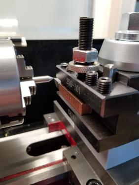
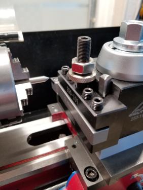
Probably adding power feed to the lead screw at the tail stock end. It would be nice to have a finer feed than the stock lathe provides.
Ed
EDIT: Actually the next upgrade will be the cam lock for the tailstock. I've had the kit from LMS for quite some time now so it's time I made use of it.
Posts: 794
Threads: 52
Joined: Mar 2012
Location: Rochester, NY
The following 2 users Like rleete's post:
EdK (05-27-2024), Vinny (05-30-2024)
05-27-2024, 06:36 PM
(This post was last modified: 05-27-2024, 06:38 PM by rleete.)
I snagged a scrap gearmotor almost 30 years ago to do just that, after seeing it on a website. It still sits on a shelf, as files and sandpaper are much easier.
And we know you printed those parts simply because you love to play with CAD and the printer. Don't worry, we won't tell anyone.
Full of ideas, but slow to produce parts
Posts: 8,888
Threads: 320
Joined: Feb 2012
Location: Arizona/Minnesota
(05-27-2024, 04:20 PM)EdK Wrote: And we know you printed those parts simply because you love to play with CAD and the printer. Don't worry, we won't tell anyone.

Posts: 8,888
Threads: 320
Joined: Feb 2012
Location: Arizona/Minnesota
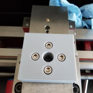
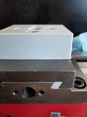
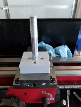
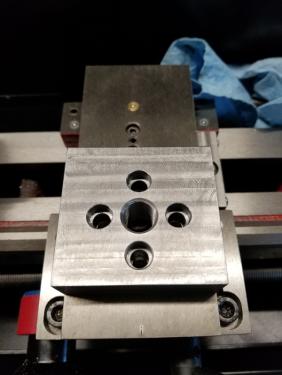
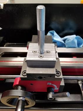
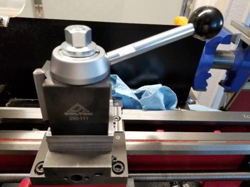
I finally did some machining in my shop yesterday and today. Got the riser block finished for the AXA QCTP.
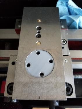
It's not actually bolted down yet since I still have to make the round piece that goes into the cross slide that the riser block will bolt to. I've got to get my lathe back together now so I can make that.
Ed
Posts: 8,888
Threads: 320
Joined: Feb 2012
Location: Arizona/Minnesota
The following 3 users Like EdK's post:
rleete (06-03-2024), Vinny (06-03-2024), Highpower (06-03-2024)
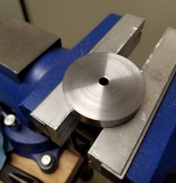
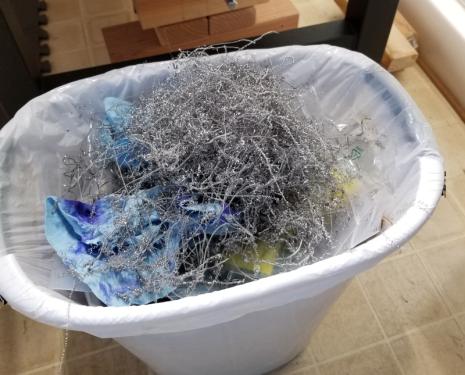
I didn't get into the shop until after lunch so not much done today. I got the disk to thickness. I had bought the disk from McMaster and it was advertised as being 1/2" thick but it was 5/8". I guess that's better than being narrower than advertised. Numerous .005" passes later I got it down to .3595. That generated a lot of swarf.
I drilled a hole in the center so it can be mounted on a mandrel for turning the OD and cutting the step in it.
Ed
Posts: 794
Threads: 52
Joined: Mar 2012
Location: Rochester, NY
Halfway there.
If you enlarge the hole to match the riser block, you can use that as a template for marking out the holes.
Full of ideas, but slow to produce parts
Posts: 8,888
Threads: 320
Joined: Feb 2012
Location: Arizona/Minnesota
(06-03-2024, 09:10 AM)rleete Wrote: Halfway there.
If you enlarge the hole to match the riser block, you can use that as a template for marking out the holes.
I'm going to use the PLA model for marking out for the holes. That is after I've made sure the PLA model and steel riser block bolt together properly. I did buy two disks just in case I screw up the first one.

Ed
Posts: 4,493
Threads: 187
Joined: Feb 2012
Location: Missouri, USA
The following 1 user Likes Highpower's post:
EdK (06-04-2024)
(06-02-2024, 08:50 PM)EdK Wrote: ... I had bought the disk from McMaster and it was advertised as being 1/2" thick but it was 5/8". I guess that's better than being narrower than advertised.
Ed
Better to be looking at it than looking FOR it as Keith Fenner would say.
Willie
