Zeroing a universal mill table
#1
I struck a problem a little while ago when doing some stub milling on the Victoria U2 universal mill. When taking more than one pass with a face mill in the horizontal spindle, I was left with a step between the two cuts, I didn't measure the step but it was visibly obvious and definitely enough to catch a fingernail on. I puzzled over it at the time and then I had a bit of a lightbulb moment a few days ago, I think the table X axis is not square to the spindle. Can anyone tell me the correct procedure for setting the table square to the horizontal spindle? Haven't been able to find any info on this anywhere. I'm thinking that if I mount an indicator on the table so that it probes the face of the column, moving the table across in the X axis will sweep the indicator across the machined face of the column. I tried this today and I get a difference of .007" across the column which is about a foot or so wide. Before I go and make the adjustment based on that I thought I'd better check that I'm not missing something. Also this assumes that the face of the column is square to the spindle- is this a reasonable assumption? I guess I could check that by turning an indicator in the spindle with the tip on the column face, like tramming a vertical head.
Given that these machines are intended to be swiveled to various angles for spiral milling etc, there must be a right way to set it back to zero, let me know if I'm barking up the wrong tree.
Lathe (n); a machine tool used in the production of milling machine components.

Milling Machine (n); a machine tool used in the production of lathe components.
Reply
Thanks given by:
#2
That is the correct procedure.
Reply
Thanks given by: Pete O
#3
Pete,

You should be able to tram the horizontal spindle to the table the same as with a vertical spindle. Just mount your indicator 6" or so off center form the spindle and sweep it 360º along the surface of the table. When the table is perpendicular to the spindle, the indicator will read the same all the way around.

Tom

So I looked at a pic of your mill and it wasn't what I was thinking. You need to sweep the back edge of the table and adjust it so the indicator reads the same at 3:00 and 9:00. That will align the table perpendicular to the spindle.

Tom
[Image: TomsTechLogo-Profile.png]
Reply
Thanks given by:
#4
Pete, I'm trying to picture the setup you used. I'm thinking you had a face mill mounted in the NMTB 40 spindle socket and were raising (or lowering) the Z-axis for the second cut across the workpiece. If that's the case and you got a step, it could be the Z-axis that's allowing the table to nod away from the column. Might be worth checking the Z-axis gibs to see if they need snugging up a bit.

If that's not it, I'd do the sweep thing on the face of the column, like you said. You've got just under 9" of flat surface to sweep in a full circle - Nice because it just misses the end of the gear bearing block below the spindle, and it's above any area that would have the knee sliding on it. If that surface sweeps true, mounting the indicator on the table will work. If it isn't true enough, you might be able to clamp a really straight flat bar against one of the slots on the table (the cleanest one) to run the indicator against, with the indicator stuck to the column.
Mike

If you can't get one, make one.

Hawkeye, proud to be a member of MetalworkingFun Forum since Jan 2013.
Reply
Thanks given by:
#5
Ok it's taken me a while to get back- I took a heap of measurements of the mill and made some adjustments. Stand by for a pile of photos.

This is the type of cut I was making when I found the problem; with a face mill mounted in the NMTB40 horizontal spindle, I needed to take two passes across a workpiece by moving the knee in the Z-axis.
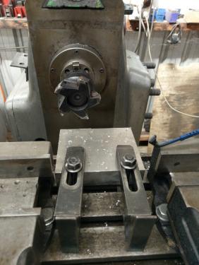
   

Because of the position of the cut on the workpiece and the width of the area to be machined, I needed to take two vertical side-by-side passes, I took one pass by raising the knee, then moved the table across in X and took the second pass by lowering the knee. The result was that the there was a step between the two cuts. I have done the same on this piece of aluminium just to demonstrate the problem I was having. You can see the step where the cuts overlap; I didn't measure it but it's not acceptable.
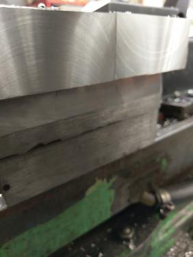
   

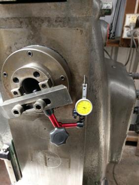
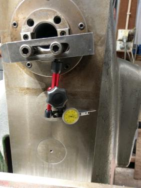
After my last post, I decided to take a heap of measurements on the machine to see where it was at. I took the vertical milling attachment off (wish it was as quick to install and tram that thing as it is to remove it) and set to with a DTI. Firstly indicating from the spindle to the column face to check how square the spindle is to the face. There is no way to adjust this.
Firstly with the arm short,
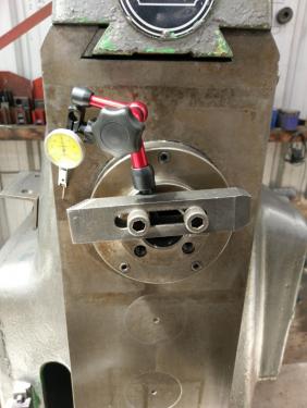


The face of the column here is a bit uneven from where the vertical attachment has been clamped on for decades. I extended the arm to indicate off a part of the column face that is not touched by either the vertical attachment nor the knee.
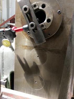


I got a reading of .024mm across a 210mm sweep. That's just under a thou in 8 1/4'. Good or bad, it is what it is.

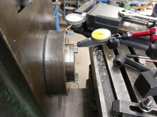
I put a 1" horizontal milling arbor in the spindle, took readings around it to find the straight side and indicated off it to check the alignment of the Y-axis movement to the spindle axis.
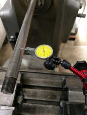
   
I took a reading along the top of the arbor to check the parallelism of these two axes in the vertical plane; result was pretty poor- 0.12mm in 200mm (.0047" in 8")
Indicating along the side of the arbor to check the alignment of the Y-axis to the spindle in the horizontal plane, a much more pleasing .004mm in 200mm (.00015" in 8")

I checked the spindle runout both on the inside taper and o the outside surface. Both were less than one increment on a .002mm DTI.
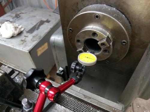


Knowing where the machine is at in these areas (I know I haven't checked straightness of any of the ways with these measurements), it seems to me that it is pretty good everywhere except for the sag in the Y-axis which will result in steps between parallel cuts when vertical milling along the X-axis but not in the step I'm getting between the Z-axis passes when stub milling.

I went through two procedures to align the table at 90 degrees to the spindle. Firstly by mounting an indicator on the table and passing it across the face of the column; it was .007" out initially from one side to the other. I adjusted the table and got it to .007mm (.00027") across the 210mm (8 1/4").
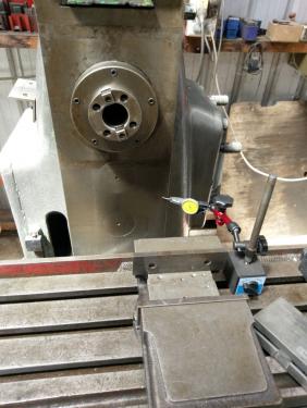
   
I took a test cut on that aluminium block passing the block across the face mill in the X axis. I was not happy with the result, no cross-hatching, the leading edge was cutting but the trailing edge of the cutter was clearing when I passed the table from left to right.

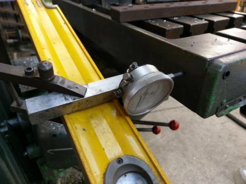
I decided to try the other suggested method of aligning the table- indicating from the spindle to the rear of the table. I was reluctant with this initially as the rear face of the table does not have the appearance of a precision surface- this is probably due to it being painted at least twice by the apprentices in the last 60 years; a bit of a cleanup revealed a better looking surface. I mounted a carpenters level to the spindle to provide a rigid arm (doesn't need to be straight, just rigid)
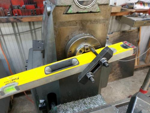
   
clamped an indicator on the outboard end and read off the back of the table at both ends by rotating the spindle 180 degrees.
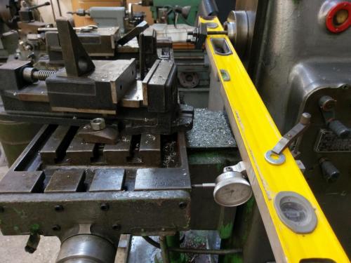


I didn't write down the initial reading but from memory it was about .007"; this is with a distance of 45" between the two ends of the swing. I adjusted it again, best I could get it was .01mm in 1140mm (.0004" in 45"). I called that near enough.

I mounted my test block of aluminium to the table again to take some test cuts. Firstly a couple of passes in the X-axis. Got a decent cross-hatched pattern which was encouraging- I didn't get a great finish but my machine can't spin this cutter fast enough for aluminium plus there was some built-up-edge on the inserts by the time I'd made the cut.
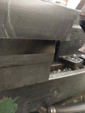
   

I moved the table in .020" and took two passes in the Z-axis; raised the knee for the first pass, moved across and lowered the knee for the second pass. I got the same problem that I started out with- a major step between the two cuts. That second photo at the top of this post is actually of this cut.

I decided to try attacking it a different way; taking both cuts with the knee moving downward. The knee is powered but I figured there is a fair bit of load to raise that knee and maybe that has something to do with it. I moved in another .020", took one pass with the knee going down, then went the long way around to get the cutter above the work and take the second pass with the knee also going down. The result was heaps better. Again, not a great finish, but there is no discernible step between the two cuts.
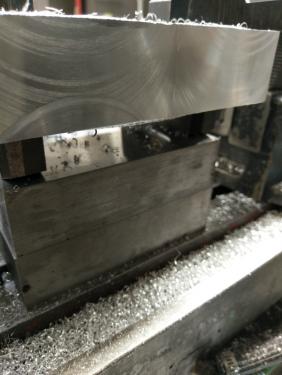
   

I was going to attach a close-up photo of that last cut but I've reached the limit per post.

I'm keen to receive any feedback or advice on this. The piece I was having the problem with is the overarm that I am mounting the j-head to for the frankenmill project. I need to cut a flat face on either side at one end to attach the cheek plates. The only way I could figure to mount the big overarm casting in the mill was parallel to the table which requires the surfaces to be milled in two passes in the Z axis.
Lathe (n); a machine tool used in the production of milling machine components.

Milling Machine (n); a machine tool used in the production of lathe components.
Reply
Thanks given by:
#6
When using a mill all movement of the knee should in the up direction. This includes alignment and when cutting. There has to be some clearance otherwise the knee cannot move and the clearance will cause differences in taking a cut moving the knee up & moving it down. Cutting the end of a thick plate as you are should be performed using the table feeding across the material, not the knee.
Reply
Thanks given by:
#7
Stan I get that the way to mill that piece of plate would be to pass it across the cutter in the X axis but it was a test piece for a cut that I cannot do in that way. I need to mill a flat surface on the side of the mill overarm in order to fix a cheek plate to each side of the overarm, there will then be a frontal piece bolted and dowelled to the front edge of those cheek plates, to which the j-head will be mounted. A few more photos to illustrate.
This is where I need a flat face, parallel to the long axis of the overarm. In this photo you can see where I have made an attempt to machine this face, the surface is stepped between the two passes of the cutter as described and demonstrated above.
   

I need a nice flat face here on each side to affix a cheek plate, this photo sort of shows where that will be attached
   

There will be one of these plates on each side; the top of the plates will be milled flat and a third plate bolted down to the top of the two cheek plates and the top of the overarm. The front surface of these three plates will then be milled to a flat plane to which the adaptor plate will be fixed.

The overarm casting is 35" long and weighs 47kg or 103lb. It's shaped like a massive bar of soap and is just as easy to hold onto.


Because the rear edge of the cut is below the surface of the casting, I need to run the cutter along that edge, which is what necessitates making the cut in the Z axis. I am 100% open to suggestions as to how else I might attack this; you know me well enough to know that is a genuine statement and not a smartarse comment. I can't see how I can secure the thing standing on end, I have a 12" x 12" angle plate that usually looks big but not big enough to stand this thing up and take the cuts in X.

Seeing that I had already busted a gut lifting that thing onto the table for these photos, I thought I may as well go ahead and try a cut. Clamping the sucker down is interesting


I took a .010" cut, firstly by moving the knee upwards with the cutter at the rear part of the cut. I then went the long way around to bring the cutter above the work for the second pass, again moving the knee upwards. As it happened, I wasn't able to raise the knee high enough to take the face mill fully off the cut at the bottom of the piece so it was still cutting as I moved it across the bottom edge. This photo shows the finished result. The surface does not have a pretty finish but more importantly THERE'S NO STEP! Thumbsup
   
I couldn't give a toss about the appearance of the finish as it will be completely and permanently concealed behind the cheek plate, probably with a little 620 for good measure. Just need it to be flat. Running a finger or a fingernail across this surface, I can not feel where the two cuts meet.

I still have the opposite side to do, like I said I am very receptive to suggestions about how to do this better.


Just as an aside, I have decided that I need to stop whining about stub milling after seeing this guy's videos:
https://www.youtube.com/watch?v=Jpp17Sir0CI
Lathe (n); a machine tool used in the production of milling machine components.

Milling Machine (n); a machine tool used in the production of lathe components.
Reply
Thanks given by:
#8
I now better understand the need to make your cuts vertically and you've done as best as can be expected. Really don't have any recommendations other than position yourself "upstream" of the cut. I'm guessing you do not currently have access to a vertical mill thus the project at hand.
Reply
Thanks given by:


Users browsing this thread: 1 Guest(s)