Frankenmill: Bridgeport J head onto Victoria U2
#51
A little more progress...
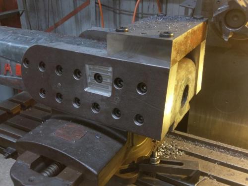
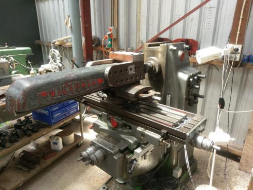
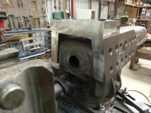
I machined the ends of the top plate parallel with the top edge of the cheek plates, then indicated the vice to the Y-axis of the mill and machined the front faces of the cheek plates and top plate.
The two recesses machined into the cheek plates can be seen in the first two photos. I didn't like the large radius of the insert end-mill in the previous post, so I refinished them with a 12mm HSS end mill, this is a better fit for the DRO bracket. I'll make a similar bracket and arm to mount the MachTach display and probably VFD controls on the side opposite the DRO.
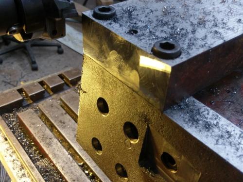


I machined the two sides of the 1.25" thick front plate by chucking it in the lathe and facing both sides.
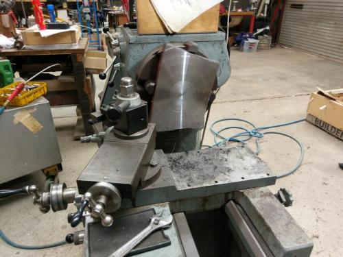
   
I milled the two long sides parallel, the shorter of these sides was cut with the oxy and it milled just fine so my fears of hardening the edges with the oxy cut thankfully didn't happen. Blurry photo below shows the front plate propped in position on some parallels that are clamped to the underside of the overarm. It needs to be dowelled and bolted to the front edges of the three other plates.
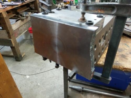
   
Machining the two remaining oxy-cut sides of the front plate promises to be a pain, haven't figured out exactly how I'll attack that yet.
Lathe (n); a machine tool used in the production of milling machine components.

Milling Machine (n); a machine tool used in the production of lathe components.
Reply
Thanks given by:
#52
Coming along nicely, Pete. Thumbsup

It's interesting to see a machine work on itself. 

Tom
[Image: TomsTechLogo-Profile.png]
Reply
Thanks given by:
#53
(02-09-2019, 07:19 AM)Pete O Wrote: Machining the two remaining oxy-cut sides of the front plate promises to be a pain, haven't figured out exactly how I'll attack that yet.

I'd indicate a bar parallel to the Z axis on your horizontal mill and use it as a stop against the already machined edge.  Slap in your face mill and go to town.
Reply
Thanks given by:
#54
...and sawing off the cut edge before you mill it will help immensely.
[Image: TomsTechLogo-Profile.png]
Reply
Thanks given by:
#55
(02-09-2019, 10:48 AM)Dr Stan Wrote: [I'd indicate a bar parallel to the Z axis on your horizontal mill and use it as a stop against the already machined edge.  Slap in your face mill and go to town.

I had trouble picturing what you were saying Stan until I realised that by Z axis you're referring to the horizontal spindle axis (I think?). I've always thought of the vertical axis as the Z.
If I understand you correctly, that would be good to get the sides machined at 90 degrees to the top & bottom. That's no difficulty; the challenge here is that the sides have an internal angle where the top plate meets the cheek plate.
It occurred to me that I may be better off leaving the sides of the front plate wider than the front of the cheek plates, also with a straight edge, so that the internal corner will provide a hand hold for sliding the overarm in & out. There's no crank function for this and once the new head is hanging off the front, it may be a challenge to extend & retract the overarm for horizontal milling.

(02-09-2019, 11:37 AM)TomG Wrote: ...and sawing off the cut edge before you mill it will help immensely.
That part of the plan will definitely be easier if I don't put in the internal corner.
Lathe (n); a machine tool used in the production of milling machine components.

Milling Machine (n); a machine tool used in the production of lathe components.
Reply
Thanks given by:
#56
(02-09-2019, 05:18 PM)Pete O Wrote: I had trouble picturing what you were saying Stan until I realised that by Z axis you're referring to the horizontal spindle axis (I think?). I've always thought of the vertical axis as the Z.

Actually the Z axis is always the center line of the spindle.
Reply
Thanks given by: Pete O
#57
Given the amount of work you've already put into this project adding a gear rack as an insert into one of the flat surfaces of the overarm and a spur gear and handle on the back side of the mill would seem to be a walk in the woods. Big Grin  That way you could easily move the overarm.

Or you could really go overboard and use your shaper to cut a gear rack right into one side of the overarm. Drool
Reply
Thanks given by:
#58
This week's progress:
I machined the sides of the front plate; decided it would look better with a straight edge rather than following the angles of the cheek & top plates, so here's how it interfaces with the front of those components
   
Not enough there for a useful grip by the time I had cleaned away the oxy cut. Perhaps I should go with Stan's suggestion of a gear drive to extend & retract the overarm. If I live that long. Rotfl

The front plate with six 5/8 holes drilled with a .050" deep counterbore, also two 10mm dowel holes. All these components are dowelled to ensure they go back precisely where they belong after painting.
   

The front surface of the cheek & top plates dowelled, drilled and ALMOST tapped 5/8 UNF to accept the front plate. Whilst I had the thing in position on the mill, I also cut the front of the casting itself down to .050" below the face of the three plates, just to ensure it doesn't foul the assembly. Nothing will be affixed to the front end of the casting.
   

I have two 5/8 x18 UNC taps out of one of those cheapy 200 piece tap & die sets, they are unfortunately not up to the task of tapping all these threads in whatever these mystery metals are. I might have a go at sharpening them- not something I've tried before- but I suspect I'll be up for the cost of a decent quality tap in that size. Until I can sort that out, these bolts won't be going any further home than this.
   

The bolt holes in the front plate are arranged to clear the final structural component- a cylindrical casting that will have the circular T-slot in the front end to mount the J-head. It needs to protrude about 3" forward of the front plate to enable the horizontal arbor supports- which are 4" thick at the dovetail- to be installed & removed with the J-head in the way.

Monday for me tomorrow- actually Sunday but that's the beauty of an 8-day shift cycle. Hopefully get some more time on this at the end of the week.
Lathe (n); a machine tool used in the production of milling machine components.

Milling Machine (n); a machine tool used in the production of lathe components.
Reply
Thanks given by:
#59
You may want to add a few more bolts to that front plate. They are in tension and don't have near the strength of the ones on the sides and top that are in shear. You don't want to sacrifice any rigidity at this point.

Tom
[Image: TomsTechLogo-Profile.png]
Reply
Thanks given by:
#60
Thanks for the comment Tom, I had a fair idea someone might mention the lack of bolts particularly into the top plate. I plan to have at least two more bolts in the top section, plus one more into each cheek plate but until the exact location of the nose casting is established (I need to install the overarm onto the mill and transfer the centerline of the hz spindle onto the front plate) I won't be able to determine exactly where the extra bolts will go. I need to be able to assemble the nose casting onto the front plate before mounting the front plate onto the front end of the overarm. The nose casting will be bolted from behind the front plate, then the front plate / nose assembly bolted onto the front of the other three plates. Once I've positioned the (yet to be cast) nose casting on the front plate, I can determine the rest of the bolt pattern. The two bolts in the top plate will go all the way through from the rear of the top plate, through the front plate and be threaded into the casting from behind after mounting the front plate / nose assembly. So lots of deep holes to be drilled yet.
Lathe (n); a machine tool used in the production of milling machine components.

Milling Machine (n); a machine tool used in the production of lathe components.
Reply
Thanks given by:


Users browsing this thread: 17 Guest(s)