Fixing a Leaky RF-45 Mill Head - Grizzly G0519
#61
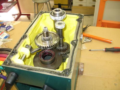
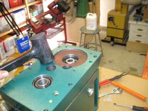
In this post I'll show the reassembly of the top and bottom halves of the head.

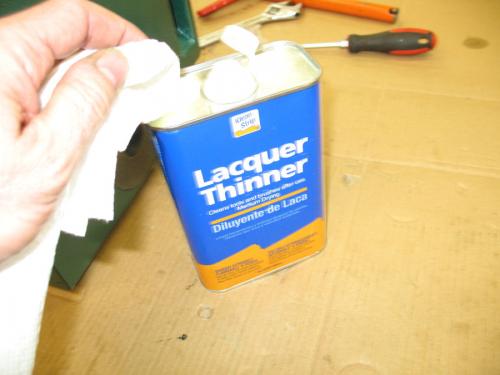
Make sure everything is correct because it will be difficult to go back from here. I used Laquer Thinner to clean the two mating surfaces. This will remove any oil, grease or paint so that the Permatex can seal properly.
   
I used white grease on the top bearings to make them slide into the lid easier. Then I added the Permatex, said a prayer that it would go together easy and carefully aligned the lid pins with the bottom.
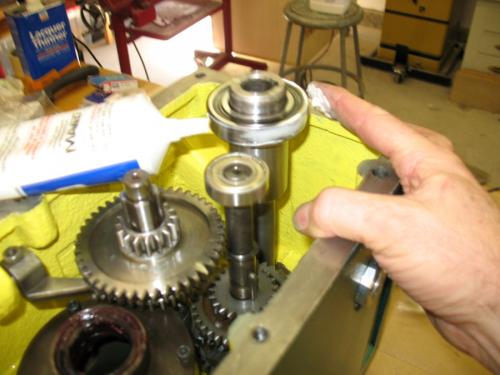


Once I got it started, I kept tapping with a rubber mallet. Many light blows are better than heavy blows. Also turn the motor shaft to make sure the gears are meshing otherwise the lid may hang up on gears that don’t mesh.
   
Once the lid was down enough for the bolts to reach, I started tightening the bolts evenly.
Keep checking that your gap between the top and bottom is even.
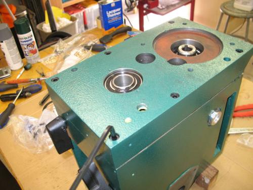
   

Gradually with light blows and even tightening the lid came all the way down. I kept checking that turning the motor shaft resulted in motion at the spindle shaft. I also tested the speed selectors a few times to make sure they worked.

The lid went all the way down and I had a nice small amount of squeeze out all the way around.
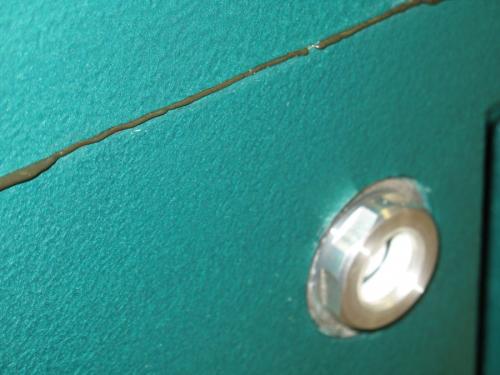
   

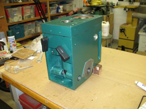
Whew!! Its together and turning the motor shaft results in the spindle shaft turning in all six gears.
   
henryarnold, proud to be a member of MetalworkingFun Forum since Apr 2012.
Reply
Thanks given by:
#62
In this post and the next one, I'll reinstall various plugs, seals and vents. I'm now on the home stretch.

Reinstall the plastic plugs that cover the Intermediate bearing shafts. You may recall we removed these by drilling a small hole and inserting a sheet metal screw to pull them out.
   
I used some white grease to make them slide in easier. I had to work the o-ring to get it to slide into the bore.
   
Installing the plugs.
   
I plugged the screw holes with paint-able caulk.
   
I next installed the motor seal with the tool I made.
   
Carefully tap it in place while keeping level.
   
Motor seal installation complete.
   
henryarnold, proud to be a member of MetalworkingFun Forum since Apr 2012.
Reply
Thanks given by:
#63
Reinstall the oil plug. I used some Teflon tape to make sure it doesn't leak.
   
Install the oil fill plug, the oil vent, and the spindle cover screws.
   
Ready to mount back on the column! I have some work to do on the mill before I reinstall the head. I'll keep you posted.
   
henryarnold, proud to be a member of MetalworkingFun Forum since Apr 2012.
Reply
Thanks given by:
#64
Mounting the head back on the mill.

I thought it would be a good idea to fill the head with oil and see if there were any leaks before mounting it back on the mill. It takes a about 3/4 of a gallon to fill the head and I believe that I need to top it off. Plan on buying a gallon of DTE heavy medium ISO 68 oil.
   
After two weeks, this is a beautiful sight and no static leaks while on the bench.
   
This is my setup for removing and reinstalling the head. The lift can handle up to 800 lbs. It is mounted on a heavy rail so I can lift something and then slide it over to the workbench.
   
After I got the head mounted back on the mill, I realized that I could take a picture looking up into the quill cavity to see if there were any leaks. In this photo you can see my bottom seal with red grease and a thin circle of black which is the Permatex #2. I don't see any oil (YES!).
   
henryarnold, proud to be a member of MetalworkingFun Forum since Apr 2012.
Reply
Thanks given by:
#65
Looking good Henry. I also decided not to install that thin rubber gasket for the piece that holds the two seals. I just used the Permatex as you did.

Ed
Reply
Thanks given by:
#66
With the head mounted back on the mill column, it's time to reinstall the motor and control boxes. The control boxes on these mills vary quite a bit and mine are modified so your installation will be different. My motor is 3 phase so if you have a 1 phase motor, your connections will be different.

Reinstall my speed, direction and tachometer control box.
   
Reinsert the motor key and carefully align it with the motor shaft on the top of the head.
   
Bolt the motor down and reconnect the wires. For three phase, they need to be in the same order as they came off otherwise the motor may turn in the wrong direction.
   
   
This is the control box for my Z Axis power feed.
   

After reinstalling my control boxes I was able to power up the mill and test the motor and gearbox. I sounds good, all speeds work, and no leaks. I am relieved.
henryarnold, proud to be a member of MetalworkingFun Forum since Apr 2012.
Reply
Thanks given by:
#67
Reinstalling the quill
Earlier I had assembled the quill but had not set the preload. The tapered bearings need to have the correct amount of tension holding the tapered inner race against the bearing surfaces. The recommended procedure is to tighten the nut all the way and then back off 1/8 of a turn. Bend up a tab on the retainer plate to hold the castellated nut in position. Some people do this adjustment again after running the machine for a while.
   
I used white grease on the quill rack gear and on the barrel. I did not like the motion of the quill with grease on the barrel so I wiped it off and used 20 wt oil instead. I'm not sure what is proper for lubrication but this should work. First reinstall your quill lock making sure the two reliefs are lined up with the quill cavity. Place some kind of soft object under you quill so if it drops, it doesn't hit your mill table. Insert the quill with a little turning motion to line up the splines with the matching spindle slots. The quill has a slot on the left side that needs to line up with a guide pin that is installed next to the return spring. Install that pin, tighten it, and then back off about a 1/4 turn, and lock the nut. Engage the down feed lock so the quill doesn't fall out.
   
Install the down feed shaft after lubricating the gears. I used white grease.
   
Install the key and spring for the down feed handle and slide the handle assembly on and screw on the retaining hand nut. That's the black handle used to release the fine down feed.
   
   
Attach the round plate that the down feed spring connects to with three screws. Install the flat head screw into the down feed shaft which clips on to the end of the down feed spring. Attaching the spring is a little tricky. You have to fiddle with the spring it until it catches. Do the next step carefully. Using gloves or a rag, turn the down feed spring counterclockwise to put tension on it. You don't have to do it in one big motion. You can do it a few half turns at a time. Each time you turn it, re-catch the down feed spring housing on the plate which has a pin to hold it. When you get the right amount of tension, the quill will return gracefully to top of it's available travel. Once the spring has the right amount of tension, replace the hand nut that holds the spring housing in place.
   
   
henryarnold, proud to be a member of MetalworkingFun Forum since Apr 2012.
Reply
Thanks given by:
#68
Reinstall the quill yoke and depth limit hardware and then the front panel. Reinstall the depth pointer.
   
I reinstalled my down feed DRO which attaches to the front panel and has a plunger which connects to the quill yoke. Install the speed selector handles.
   
All done! I played with my "new" mill for about an hour. It runs a quieter and sounds smoother. The paint on the head is much better than before so the mill looks better.

Best of all, the next morning there was no puddle of oil on my table.
   
henryarnold, proud to be a member of MetalworkingFun Forum since Apr 2012.
Reply
Thanks given by:
#69
Henry,

That must be a relief to get it done with no apparent harm to the machine. I'm a bit behind you but I'll get there soon enough. Smile

Ed
Reply
Thanks given by:
#70
(05-12-2012, 11:11 AM)EdAK Wrote: Looking good Henry. I also decided not to install that thin rubber gasket for the piece that holds the two seals. I just used the Permatex as you did.

Ed

Ed,
Thank you and thanks for all your help.
Thank you everyone for your comments, suggestions, and encouragement. I think doing this job has shown me once again the great value of forums. It would have been much more daunting to do this work with no one to ask questions of. I relied on your experience and on posts from people who had previously rebuilt their RF-45 heads.
Henry Arnold
henryarnold, proud to be a member of MetalworkingFun Forum since Apr 2012.
Reply
Thanks given by:


Users browsing this thread: 3 Guest(s)