Posts: 4,683
Threads: 93
Joined: Feb 2012
Location: Perth, Australia
05-04-2012, 08:51 PM
(This post was last modified: 05-04-2012, 08:51 PM by Mayhem.)
Good write up thus far Henry. It is posts like this and Ed's that will be valuable resources for others. I'm looking forward to watching your progress.
A quick comment about protecting the table. I cut a piece of plywood a little larger than the table and then place a small strip of plywood on each of the long sides. These will stop the wood from moving.
Hunting American dentists since 2015.
Posts: 170
Threads: 9
Joined: Apr 2012
Location: Southern California
(05-04-2012, 05:33 PM)Highpower Wrote: Great thread Henry! And the pictures are terrific. 
You've really got that mill decked out to the max, and did an awesome job.

Thanks. I'll try to do some pictures later on my mods if there is some interest.
henryarnold, proud to be a member of MetalworkingFun Forum since Apr 2012.
Posts: 170
Threads: 9
Joined: Apr 2012
Location: Southern California
05-04-2012, 11:05 PM
(This post was last modified: 05-04-2012, 11:06 PM by henryarnold.)
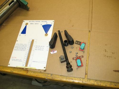
Here's the parts that were removed with the front panel including the depth limit, switches which are no longer used on my mill, the front panel, and the gear selectors.
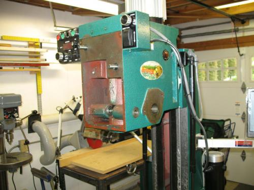
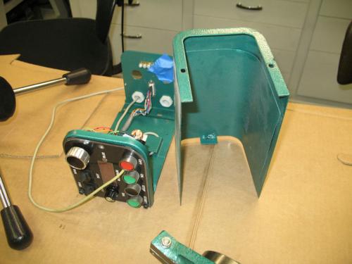
Next I need to remove the two control boxes. These boxes vary quite bit between RF-45 versions. On mine the left box controls speed, direction, and the tachometer. The right box controls the Z axis power feed.
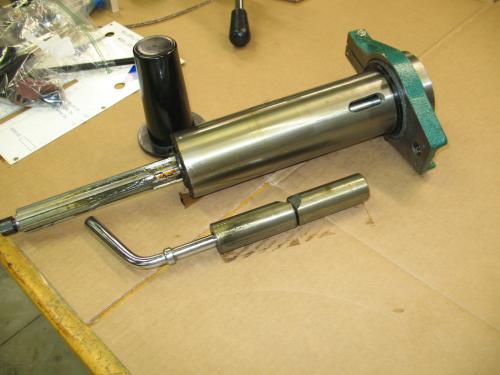
After the depth limit is removed, you can release the quill and gently remove it from the housing. Shown are the quill, the clamp, and the spindle cover. I'll show disassembly of the quill later.
henryarnold, proud to be a member of MetalworkingFun Forum since Apr 2012.
Posts: 170
Threads: 9
Joined: Apr 2012
Location: Southern California
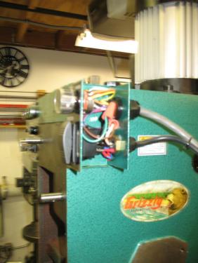
Both of my control boxes have screws from the inside that attach them to the mill head. I removed the covers and released the internal mounting screws. These boxes are usually wired to the base of the mill so they can be pushed aside freeing the head for removal.
henryarnold, proud to be a member of MetalworkingFun Forum since Apr 2012.
Posts: 170
Threads: 9
Joined: Apr 2012
Location: Southern California
05-04-2012, 11:19 PM
(This post was last modified: 05-04-2012, 11:20 PM by henryarnold.)
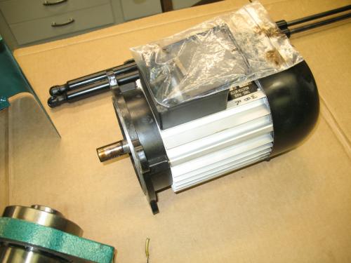
Removing the motor before removing the head will make it that much lighter. Open the junction box and make a note of the wiring before disconnecting the wires. On my mill, there are four bolts holding the motor in place. After I removed them the motor pulls straight up. Be sure to save the key which will either be on the motor shaft or inside the hole the motor shaft fits into.
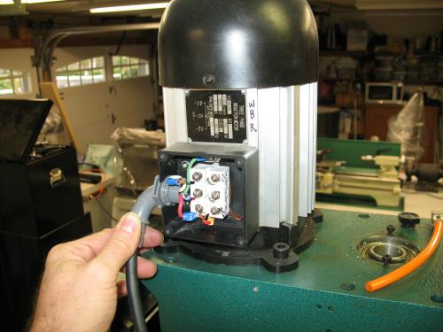
Here's my motor on the bench. I ziplock bagged parts, bolts and screws from each step so it would be easy to find things when I start putting it back together.
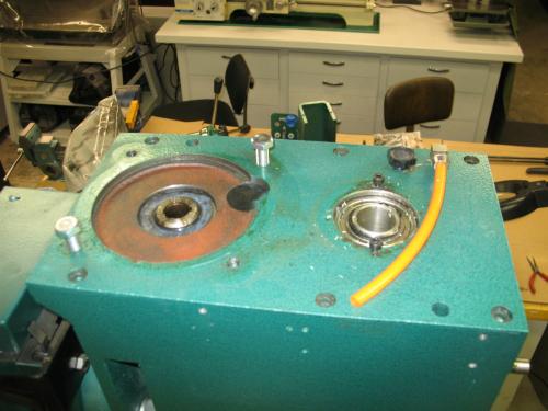
Top of the mill after the motor has been removed. The two bolts are for my lifting cable to remove the head.
henryarnold, proud to be a member of MetalworkingFun Forum since Apr 2012.
Posts: 170
Threads: 9
Joined: Apr 2012
Location: Southern California
05-04-2012, 11:24 PM
(This post was last modified: 05-04-2012, 11:33 PM by henryarnold.)
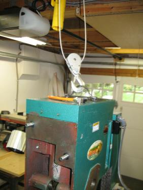
I have an overhead electric lift from Harbor Freight which is not shown in the picture. It can lift up to 800 lbs and is perfect for the head removal. It is mounted on a rail so I can slide the head over to my workbench. Once you support the head, remove the three 24 mm bolts that mount it to the yoke of the mill
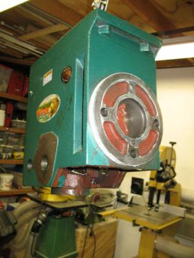
Head after removal from the mill.
henryarnold, proud to be a member of MetalworkingFun Forum since Apr 2012.
Posts: 170
Threads: 9
Joined: Apr 2012
Location: Southern California
05-04-2012, 11:39 PM
(This post was last modified: 05-04-2012, 11:42 PM by henryarnold.)
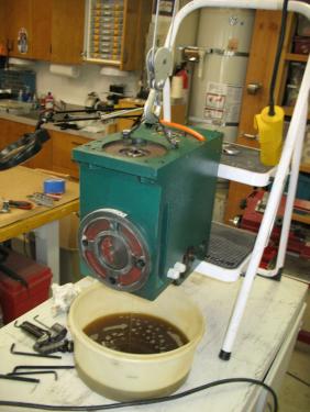
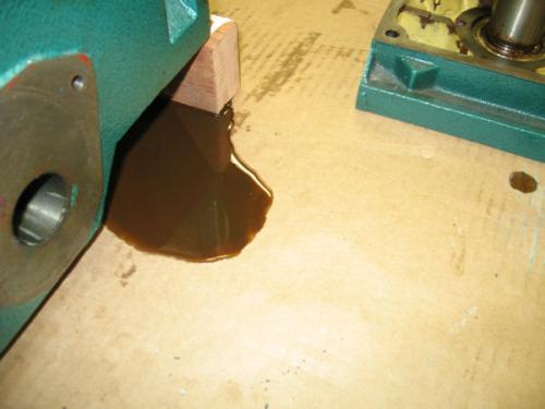
I forgot to drain the oil before removing the head so I had to do it before mov ing it to my workbench. I propped it up at an angle on the edge of a step stool and let it drain for a while. The drain plug on these mills is easy to miss. It's under neath the head near the third mounting bolt. The plug has got a hex allen head.
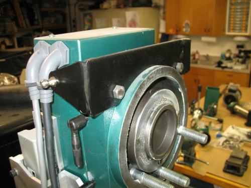
I have added a gas spring head counter balance and Z axis power feed to my mill. These are the upper gas spring mounts which I fabricated from 1/8" mild steel and two stainless ball mounts. The two electrical connections are for the motor and for the control box. The cables run throught the inside of the column down through the base to the VFD.
henryarnold, proud to be a member of MetalworkingFun Forum since Apr 2012.
Posts: 170
Threads: 9
Joined: Apr 2012
Location: Southern California
05-04-2012, 11:55 PM
(This post was last modified: 05-05-2012, 12:01 AM by henryarnold.)
Approximately 2 hours later I had the head on my workbench. I forgot to take picture of opening up the head but it is not as hard as I had heard it was.
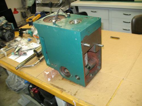
Remove the 6 bolts from the top. Lay the head on its side. At this point the oil that should have drained out already will pour on to your bench. Quickly find some rags to mop it up

Use a utility knife and a straight edge to score the joint all the way around. If you don't do this, you will get a more ragged break where the case separates.
I used a hardwood block and mallet to gently tap on the rear lip and a very narrow front lip where the front panel sits. Alternate from the back to the front and gradually the case will come apart. I did not use any prying tools between the case halves so that I would not mar the faces. My running gear came out with the top.
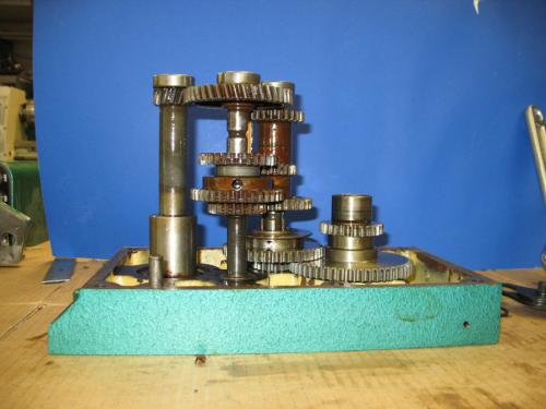
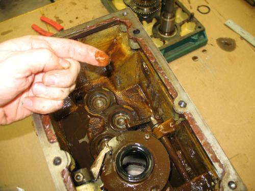
Here's the interior of my head. The brown stuff looks like rust but it is not rust. I'm not sure what it is but it looks and feels like a polishing compound which makes no sense. This contamination is reason enough to replace all bearings. There was a brown sludge in the bottom of my gearbox.
Tomorrow I'll continue with the tear down of the gearbox.
henryarnold, proud to be a member of MetalworkingFun Forum since Apr 2012.
Posts: 4,513
Threads: 139
Joined: Feb 2012
Location: Kempton Park. South Africa
Henry,
Excellent


DaveH
Posts: 8,888
Threads: 320
Joined: Feb 2012
Location: Arizona/Minnesota
Henry,
That brown sludge is rather disgusting. I was pleasantly surprised when I found very little foreign matter in my mill head.
Ed


