05-19-2015, 07:52 AM
I mentioned in the 'Today's Project' thread the other day that I was building a furnace. I'll try and remember to take photos as I go and we'll see how this progresses.
I feel I should mention at the outset that I have never built a furnace before. In fact I have never operated a furnace. Indeed, I have never even seen a furnace operating! Just seemed like a good idea to be able to produce my own castings and lumps of metal.
Given my absolute ignorance, I will be deriving the entire design from this book, purchased online about 12 months ago:
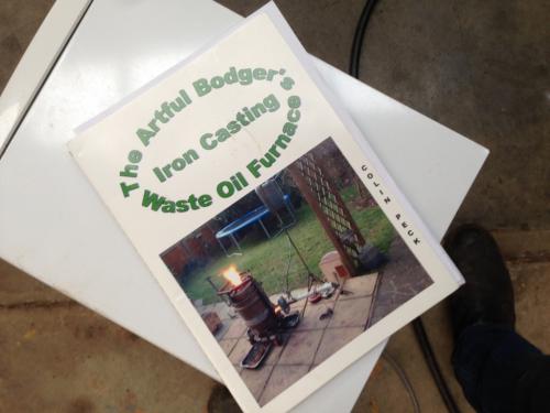
I will certainly be open to any suggestions for improvements or alterations as I go, so if you know a better way please chime in, otherwise it will be very closely based on Colin's book.
The author's furnace is unashamedly rough-and-ready in it's construction, to the extent that he does all his metal cutting with an arc welder cranked up hot! I guess it's not meant to be a showpiece, and it certainly melts some metal. Hopefully mine will too.
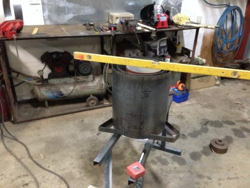
The furnace has 3 concentric metal tubes: the outer skin, outer former and inner former. The space between the inner and outer formers is filled with castable refractory, and the inner former removed once the refractory has set. The space between the outer former and the outer skin is to be filled with insulation. I'd waited too long to find a suitable treasure trove of tubes and drums to make the 3 required tubes from, so I got some 2mm sheet cut and rolled by the local guys I buy most of my metal from. I then welded the seams of the 2 main tubes, the skin and the outer former, and rolled the inner former to shape around 3 250mm plywood discs that will maintain it's shape while ramming the refractory.
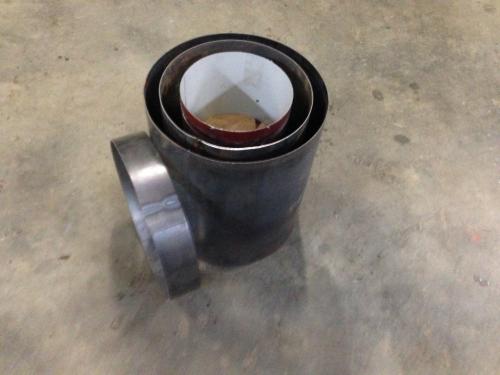
The extra ring is for the lid, same diameter as the outer skin.
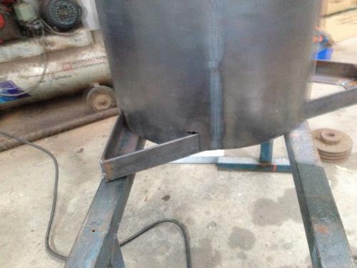
Today's progress involved getting the base frame cut and welded up, so the outer former sits on the flat of the angles:
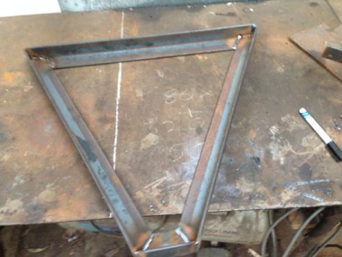
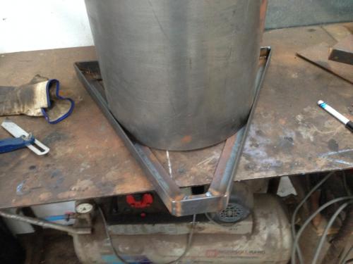
Then cutting slots into the bottom of the outer skin so it sits down over the angle iron frame.
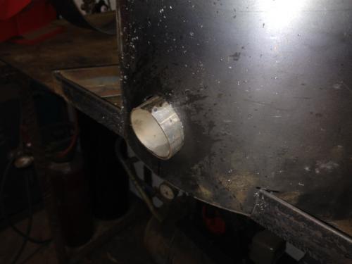
I couldn't bring myself to use the arc welder to do the cutting, so I used a holesaw to cut holes for the tap hole through the skin and outer former; this is for tapping off metal melted directly in the base of the furnace, i.e. without a crucible. It is angled up into the centre. I had to cut-and-shut a short offcut of exhaust tubing to the desired diameter for the tap-hole former; I'll weld this in place after all the basic setting out is done
I then started nutting out the location of the big hole business for the air blower inlet and the preheater outlet; I was part way through roughly sketching this out on the outer skin when my good lady called me for the evening repast. I had promised to spend the evening indoors after dinner, so that's it for today.
I feel I should mention at the outset that I have never built a furnace before. In fact I have never operated a furnace. Indeed, I have never even seen a furnace operating! Just seemed like a good idea to be able to produce my own castings and lumps of metal.
Given my absolute ignorance, I will be deriving the entire design from this book, purchased online about 12 months ago:
I will certainly be open to any suggestions for improvements or alterations as I go, so if you know a better way please chime in, otherwise it will be very closely based on Colin's book.
The author's furnace is unashamedly rough-and-ready in it's construction, to the extent that he does all his metal cutting with an arc welder cranked up hot! I guess it's not meant to be a showpiece, and it certainly melts some metal. Hopefully mine will too.
The furnace has 3 concentric metal tubes: the outer skin, outer former and inner former. The space between the inner and outer formers is filled with castable refractory, and the inner former removed once the refractory has set. The space between the outer former and the outer skin is to be filled with insulation. I'd waited too long to find a suitable treasure trove of tubes and drums to make the 3 required tubes from, so I got some 2mm sheet cut and rolled by the local guys I buy most of my metal from. I then welded the seams of the 2 main tubes, the skin and the outer former, and rolled the inner former to shape around 3 250mm plywood discs that will maintain it's shape while ramming the refractory.
The extra ring is for the lid, same diameter as the outer skin.
Today's progress involved getting the base frame cut and welded up, so the outer former sits on the flat of the angles:
Then cutting slots into the bottom of the outer skin so it sits down over the angle iron frame.
I couldn't bring myself to use the arc welder to do the cutting, so I used a holesaw to cut holes for the tap hole through the skin and outer former; this is for tapping off metal melted directly in the base of the furnace, i.e. without a crucible. It is angled up into the centre. I had to cut-and-shut a short offcut of exhaust tubing to the desired diameter for the tap-hole former; I'll weld this in place after all the basic setting out is done
I then started nutting out the location of the big hole business for the air blower inlet and the preheater outlet; I was part way through roughly sketching this out on the outer skin when my good lady called me for the evening repast. I had promised to spend the evening indoors after dinner, so that's it for today.
Lathe (n); a machine tool used in the production of milling machine components.
Milling Machine (n); a machine tool used in the production of lathe components.
Milling Machine (n); a machine tool used in the production of lathe components.


