Billy G's Die Filer
#1
Billy,

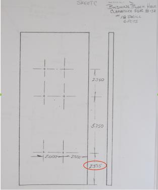
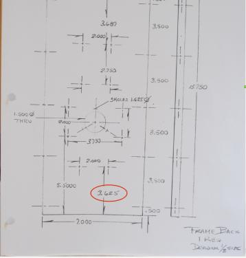
I have a couple of questions about the prints. I've attached images to help clarify what I'm trying to ask. On what I'll call the master page for the frame back you have a dimension at the bottom dimensioning two holes 3.625" from the bottom of the part. On another page called "Bushing Block Holes" those holes appear to be dimensioned 2.375 from the bottom of the part. Either I'm not interpreting the drawings correctly, probably so, or there might be an error.

Another question is about the three 6-32 holes that are around the 1.5" through hole in that same part. Are those tapped holes or clearance holes? Either way, they are going to cut into the 1.5" hole. Is that your intention?

Ed
         
Reply
Thanks given by:
#2
Ed --- 3.625 is the correct dimension not 2.375. The other 3 holes around the 1.5 thru hole are tapped holes. The center on the spindle flange. Move them if necessary. This is why I like to build before I do the plans. Sorry for the confusion. The large front and side views are Full Size Ed. You can check dimensions from them if need be. The one of the motor set up is not.

"Billy G"
Reply
Thanks given by:
#3
To fix the three 6-32 threaded holes find the print for the "Spindle Parts". Make the flange diameter 2.375 and reposition the holes to a 1.875 diameter. They should be OK there.

"Billy G"
Reply
Thanks given by:
#4
Are the plans for the Die Filer available?

Chuck
Micromark 7x14 Lathe, X2 Mill , old Green 4x6 bandsaw
The difficult takes me a while, the impossible takes a little longer.
Reply
Thanks given by:
#5
(03-04-2015, 06:43 AM)chucketn Wrote: Are the plans for the Die Filer available?

Chuck

No, I just got them from Billy so it will be a while before I have them all drawn up in CAD.

Ed
Reply
Thanks given by:
#6
(03-04-2015, 12:16 AM)Bill Gruby Wrote: To fix the three 6-32 threaded holes find the print for the "Spindle Parts". Make the flange diameter 2.375 and reposition the holes to a 1.875 diameter. They should be OK there.

"Billy G"

1.875" is what I was going to dimension them to so "great minds think alike". Smile

Ed
Reply
Thanks given by:
#7
Ed;

Due to the small bolt change I needed to change the spindle print. Here it is with only the flange change and a whole new spindle. Don't know what happened there but click on the picture and you can read it.

"Billy G"


Attached Files Thumbnail(s)
   
Reply
Thanks given by:
#8
Let's try again? ARGHHHH!!! Not gonna be my day I guess. At least you can read it better when you click and enlarge it. That 2.375 dimension is the flange OD Ed. I left the arrow off. I gotta slow down. LOL

"Billy G"


Attached Files Thumbnail(s)
   
Reply
Thanks given by: EdK
#9
I never knew Amish Cad was as difficult to master as Auto Cad etc Big Grin
Hunting American dentists since 2015.
Reply
Thanks given by:
#10
Billy,

The lower bushing block mounting holes are shown at 3.625" from the bottom on the master sheet but 2.375" from the bottom on the "Bushing Block Holes" sheet. The side view shows that to be at 3.625" so I'll go with that unless you tell me otherwise.
Also, the very top bushing block mounting holes are dimensioned at 3.687 from the top on the master sheet but on the "Bushing Block Holes" sheet if you do the math with the dimensions on that sheet, those holes are at 3.625" from the top. Can you please check the dimensions and let me know what to use?

By the way, the side view doesn't appear to be accurately to full scale. The frame back is supposed to be 15.750" tall but it's measuring at about 15.4375.

Ed
Reply
Thanks given by:


Users browsing this thread: 4 Guest(s)