Posts: 173
Threads: 2
Joined: Jun 2015
Location: Utah
I am embarassed to say this but I have had a 3-jaw chuck and backing plate blank sitting on my bench for the past 9+ months now and no time to work on it. I have a 8" Vertex Rotary Table that I acquired about 8 or so years ago. I haven't used it much due to what a pain it was to use the mill feature on my previous 3-in-1 machine. However, I decided to finally set it up with a 3-jaw chuck and start using the rotary table a bit more. Last summer I scored an inexpensive 3-jaw from ebay and a blank backing plate to mount the chuck onto my rotary table. It has been sitting on my work bench ever since because I have not had time to machine the adapter plate.
Well, I have a set of handlebar mounts to machine for a customer's bike and I could really use that 3-jaw to cut the radius on the mill. I figured it was time to get the adapter place machined so I could use it for this project and it would be completed and readily available whenever I need it in the future.
I set up the adapter plate in the 4-jaw and dialed it in. I also covered the bed, carriage and as much of the lathe as possible as I hate machining cast iron.
![[Image: a4ydmg.jpg]](http://i60.tinypic.com/a4ydmg.jpg)
I next faced the backing plate and cut the OD to size. It originally measure 8.3" and I needed to take it down to 8" exactly to match the rotary table diameter.
![[Image: 11ka5iv.jpg]](http://i60.tinypic.com/11ka5iv.jpg)
Once I got it trued and turned down, I flipped it around in the 4-jaw to machine the step to match the back side of the 3-jaw chuck.
![[Image: 21c5zsy.jpg]](http://i61.tinypic.com/21c5zsy.jpg)
Here is the little 6" 3-jaw that will be used on my 8" rotary table.
![[Image: 2q39imv.jpg]](http://i59.tinypic.com/2q39imv.jpg)
Mike.
Posts: 173
Threads: 2
Joined: Jun 2015
Location: Utah
The following 2 users Like zmotorsports's post:
EdK (06-12-2015), PixMan (06-12-2015)
Here is the mess after the lathe work is completed and just prior to removing the backing plate from the 4-jaw chuck.
![[Image: 25yu9h3.jpg]](http://i60.tinypic.com/25yu9h3.jpg)
Turning and facing processes completed and ready to drill the mounting holes. The step is .001" smaller than the backside of the chuck so it will self center onto the plate.
![[Image: 292oi7o.jpg]](http://i60.tinypic.com/292oi7o.jpg)
Chuck test fit onto the plate to ensure self-centering. I got a little cocky here but I should have test fit it prior to removing it from the lathe. Had my measurements been off I could have been chucking it back up in the lathe to make a skim cut. Luckily everything fell together perfectly. Another reason I probably shouldn't work this late at night.:willy_nil
![[Image: 2150epc.jpg]](http://i60.tinypic.com/2150epc.jpg)
Vise removed from mill table and the backing plate clamped down locating the center. I have it spaced off the table so I can drill through without hitting the table. Using my handy, dandy modified Noga/IndiCol DTI holder. Works awesome. You can also see the DRO that I have zero'd after locating center.
![[Image: 30iuk5c.jpg]](http://i58.tinypic.com/30iuk5c.jpg)
Three chuck mounting holes drilled. The bolt hole circle function in the DRO flat ROCKS!!!
![[Image: 28wkklk.jpg]](http://i62.tinypic.com/28wkklk.jpg)
I used a .375" end mill and countersunk for the socket head capscrews to sit just below flush.
![[Image: v3q9so.jpg]](http://i61.tinypic.com/v3q9so.jpg)
Next I flipped the adapter over and plugged the dimensions into the DRO for the four bolt hole pattern to match the slots in the rotary table.
![[Image: dvouug.jpg]](http://i60.tinypic.com/dvouug.jpg)
Four bolt pattern drilled and countersunk with a .625" end mill.
![[Image: if4vox.jpg]](http://i57.tinypic.com/if4vox.jpg)
Completed sitting on the rotary table.
![[Image: b6zn5s.jpg]](http://i59.tinypic.com/b6zn5s.jpg)
Mike.
Posts: 8,859
Threads: 319
Joined: Feb 2012
Location: Arizona/Minnesota
Mike,
Don't worry about hogging the thread. Hog away! I love the details you put in your posts. Keep it up please.
Ed
Posts: 2,620
Threads: 100
Joined: Dec 2014
Location: Michigan
Posts: 8,859
Threads: 319
Joined: Feb 2012
Location: Arizona/Minnesota
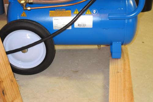
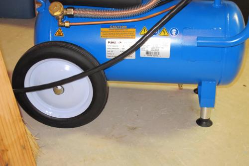
After Mike's string of posts, I'm almost embarrassed to post this but what the hell. Since I changed the wheels on my compressor to larger ones to add some height for accessing the drain valve, the feet needed to be extended so the compressor sits reasonably level. I got'r done today.
Ed
Before

After

Posts: 2,620
Threads: 100
Joined: Dec 2014
Location: Michigan
There ya go Ed, with mine (albeit larger and upright) I put it on a moving dolly so I cat roll it out of where it is (under the steps in the shop) and get to stuff stored behind it. But the drain valve is a good 4-6" off the floor.
Posts: 2,344
Threads: 53
Joined: Feb 2012
Location: Spencer MA USA
(06-12-2015, 02:47 PM)zmotorsports Wrote: Here is the mess after the lathe work is completed and just prior to removing the backing plate from the 4-jaw chuck.
Turning and facing processes completed and ready to drill the mounting holes. The step is .001" smaller than the backside of the chuck so it will self center onto the plate.
Chuck test fit onto the plate to ensure self-centering. I got a little cocky here but I should have test fit it prior to removing it from the lathe. Had my measurements been off I could have been chucking it back up in the lathe to make a skim cut. Luckily everything fell together perfectly. Another reason I probably shouldn't work this late at night.:willy_nil
Vise removed from mill table and the backing plate clamped down locating the center. I have it spaced off the table so I can drill through without hitting the table. Using my handy, dandy modified Noga/IndiCol DTI holder. Works awesome. You can also see the DRO that I have zero'd after locating center.
Three chuck mounting holes drilled. The bolt hole circle function in the DRO flat ROCKS!!!
I used a .375" end mill and countersunk for the socket head capscrews to sit just below flush.
Next I flipped the adapter over and plugged the dimensions into the DRO for the four bolt hole pattern to match the slots in the rotary table.
Four bolt pattern drilled and countersunk with a .625" end mill.
Completed sitting on the rotary table.
Mike.
Mike,
Nice work! Good to see some chips on the otherwise pristine machines. You did the right thing to cover the ways before machining cast iron, that stuff is a magnet to way lube and really gums up the works. Other than being the dirtiest metal there is, it a joy to machine. Never (or rarely) is there a chip control problem, though it can wear out the wrong HSS tools pretty quickly.
BTW, I've used end mills as counterbores in the home shop for years and it does work but keep your eyes open for a bargain on true counterbores. I found this array had fallen outside my shop one day (quite literally) and they've proven very handy. You get a true flat-bottomed counterbore and good ones break the edge of the counterbore were it meets the minor diameter.
![[Image: IMG_20130907_153702280_zps93c932a5.jpg]](http://img.photobucket.com/albums/v466/kenm10759/Dads%20shop/IMG_20130907_153702280_zps93c932a5.jpg)
Posts: 4,683
Threads: 93
Joined: Feb 2012
Location: Perth, Australia
Nice work Mike - I enjoyed reading your posts with my morning cuppa.
Ed - there is nothing wrong with your work.
Hunting American dentists since 2015.
Posts: 173
Threads: 2
Joined: Jun 2015
Location: Utah
(06-12-2015, 06:33 PM)EdK Wrote: Mike,
Don't worry about hogging the thread. Hog away! I love the details you put in your posts. Keep it up please.
Ed
(06-12-2015, 06:35 PM)Vinny Wrote: 
Thanks guys.
(06-12-2015, 07:17 PM)PixMan Wrote: (06-12-2015, 02:47 PM)zmotorsports Wrote: Here is the mess after the lathe work is completed and just prior to removing the backing plate from the 4-jaw chuck.
Turning and facing processes completed and ready to drill the mounting holes. The step is .001" smaller than the backside of the chuck so it will self center onto the plate.
Chuck test fit onto the plate to ensure self-centering. I got a little cocky here but I should have test fit it prior to removing it from the lathe. Had my measurements been off I could have been chucking it back up in the lathe to make a skim cut. Luckily everything fell together perfectly. Another reason I probably shouldn't work this late at night.:willy_nil
Vise removed from mill table and the backing plate clamped down locating the center. I have it spaced off the table so I can drill through without hitting the table. Using my handy, dandy modified Noga/IndiCol DTI holder. Works awesome. You can also see the DRO that I have zero'd after locating center.
Three chuck mounting holes drilled. The bolt hole circle function in the DRO flat ROCKS!!!
I used a .375" end mill and countersunk for the socket head capscrews to sit just below flush.
Next I flipped the adapter over and plugged the dimensions into the DRO for the four bolt hole pattern to match the slots in the rotary table.
Four bolt pattern drilled and countersunk with a .625" end mill.
Completed sitting on the rotary table.
Mike.
Mike,
Nice work! Good to see some chips on the otherwise pristine machines. You did the right thing to cover the ways before machining cast iron, that stuff is a magnet to way lube and really gums up the works. Other than being the dirtiest metal there is, it a joy to machine. Never (or rarely) is there a chip control problem, though it can wear out the wrong HSS tools pretty quickly.
BTW, I've used end mills as counterbores in the home shop for years and it does work but keep your eyes open for a bargain on true counterbores. I found this array had fallen outside my shop one day (quite literally) and they've proven very handy. You get a true flat-bottomed counterbore and good ones break the edge of the counterbore were it meets the minor diameter.
![[Image: IMG_20130907_153702280_zps93c932a5.jpg]](http://img.photobucket.com/albums/v466/kenm10759/Dads%20shop/IMG_20130907_153702280_zps93c932a5.jpg)
Thanks. I agree about counterbores. I bought a set about 15 years ago and and use them on occassion. I should probaly use them more than I do as I generally just grab an end mill.
(06-12-2015, 07:18 PM)Mayhem Wrote: Nice work Mike - I enjoyed reading your posts with my morning cuppa.
Ed - there is nothing wrong with your work.
Thanks.
Mike.
Posts: 214
Threads: 19
Joined: Oct 2014
Location: SOUTH AFRICA,KZN,DURBAN
Ditto here as well Mikey
We need the action, keeps the place alive, gets us thinking and learning all in one go and the Dudes get to say a piece.
So win win all round. Somebody has to fill the blank pages here, and who better than an old hand like U.
U just keep 'em rolling in.
We appreciate the creativity and problem solving. "Tis obvious U one heavy experienced Mack ( Motor Mechanic, we say down here )
All the best
aRM
|
![[Image: a4ydmg.jpg]](http://i60.tinypic.com/a4ydmg.jpg)
![[Image: 11ka5iv.jpg]](http://i60.tinypic.com/11ka5iv.jpg)
![[Image: 21c5zsy.jpg]](http://i61.tinypic.com/21c5zsy.jpg)
![[Image: 2q39imv.jpg]](http://i59.tinypic.com/2q39imv.jpg)
![[Image: a4ydmg.jpg]](http://i60.tinypic.com/a4ydmg.jpg)
![[Image: 11ka5iv.jpg]](http://i60.tinypic.com/11ka5iv.jpg)
![[Image: 21c5zsy.jpg]](http://i61.tinypic.com/21c5zsy.jpg)
![[Image: 2q39imv.jpg]](http://i59.tinypic.com/2q39imv.jpg)


![[Image: 25yu9h3.jpg]](http://i60.tinypic.com/25yu9h3.jpg)
![[Image: 292oi7o.jpg]](http://i60.tinypic.com/292oi7o.jpg)
![[Image: 2150epc.jpg]](http://i60.tinypic.com/2150epc.jpg)
![[Image: 30iuk5c.jpg]](http://i58.tinypic.com/30iuk5c.jpg)
![[Image: 28wkklk.jpg]](http://i62.tinypic.com/28wkklk.jpg)
![[Image: v3q9so.jpg]](http://i61.tinypic.com/v3q9so.jpg)
![[Image: dvouug.jpg]](http://i60.tinypic.com/dvouug.jpg)
![[Image: if4vox.jpg]](http://i57.tinypic.com/if4vox.jpg)
![[Image: b6zn5s.jpg]](http://i59.tinypic.com/b6zn5s.jpg)


![[Image: IMG_20130907_153702280_zps93c932a5.jpg]](http://img.photobucket.com/albums/v466/kenm10759/Dads%20shop/IMG_20130907_153702280_zps93c932a5.jpg)