Posts: 968
Threads: 67
Joined: Apr 2015
Location: Australia
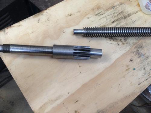
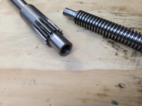
I finally got the feedscrew repair finished on my lathe.
I had cut the replacement 1" 5tpi l/h acme screw months ago, got the outer dimensions of the nut finished last week after I finally got the mill up and running, yesterday i took the feedscrew out and took it to a friend's place, cut it in two using his chop saw (the point of no return!) and used his lathe to mate the two pieces.
Outer diameter at the plain section in front of the drive gear is 0.900, I bored it to 0.600 (actually ended up 0.6004) and 1.100 deep, then turned the male section on the new screw to 0.598" and 1.00 long.


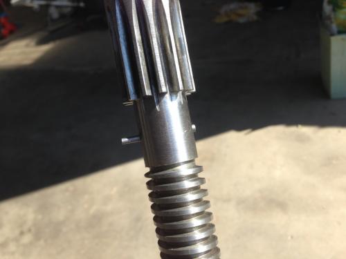
Brought it home and mated the two pieces with some Loctite 620.
I left it overnight, then cross-drilled and reamed to take a small taper pin. Inserted the pin also with 620.

Left it for an hour or so then cut the ends off the pin and filed them flush. I have fitted the new screw and nut, and will have to get accustomed to working with .002 backlash on the crossfeed where I used to have about .042.
Lathe (n); a machine tool used in the production of milling machine components.
Milling Machine (n); a machine tool used in the production of lathe components.
Posts: 3,003
Threads: 51
Joined: Apr 2012
Location: Ontario
The following 1 user Likes f350ca's post:
EdK (09-01-2015)
(08-31-2015, 08:08 PM)EdK Wrote: (08-31-2015, 08:05 PM)f350ca Wrote: Started making more cedar shingles to finish the shop.
...
Figure I need about 6 million shingles to cover the wall.
Isn't that the mechanism Sadie took off on? She decide to come back then, huh? Probably got hungry. 
Ed
She's taken to using the new ATV, it rides better.
Free advice is worth exactly what you payed for it.
Greg
Posts: 44
Threads: 3
Joined: Nov 2013
Location: Edmonton, Canada
The following 4 users Like johnnyc14's post:
EdK (09-01-2015), zmotorsports (09-01-2015), aRM (09-01-2015), Pete O (09-02-2015)
johnncyc14, proud to be a member of MetalworkingFun Forum since Nov 2013.
Posts: 173
Threads: 2
Joined: Jun 2015
Location: Utah
That looks good Johnny. What did you use for the engine turned look?
Mike.
Posts: 44
Threads: 3
Joined: Nov 2013
Location: Edmonton, Canada
The following 1 user Likes johnnyc14's post:
zmotorsports (09-02-2015)
(09-01-2015, 01:24 PM)zmotorsports Wrote: That looks good Johnny. What did you use for the engine turned look?
Mike.
Thanks Mike, I just used a 2 inch 3M Scotchbrite Roloc disc in the drill chuck. I ran the machine at 200 rpm and just brought the disc into light contact for 3 or 4 seconds in each position. I spaced the contacts on 1 inch centres starting in the centre of the panel. It was easier than trying to polish the stainless to an even finish.
johnncyc14, proud to be a member of MetalworkingFun Forum since Nov 2013.
Posts: 173
Threads: 2
Joined: Jun 2015
Location: Utah
(09-01-2015, 09:23 PM)johnnyc14 Wrote: (09-01-2015, 01:24 PM)zmotorsports Wrote: That looks good Johnny. What did you use for the engine turned look?
Mike.
Thanks Mike, I just used a 2 inch 3M Scotchbrite Roloc disc in the drill chuck. I ran the machine at 200 rpm and just brought the disc into light contact for 3 or 4 seconds in each position. I spaced the contacts on 1 inch centres starting in the centre of the panel. It was easier than trying to polish the stainless to an even finish.
Thanks. Nice job, it turned out great.
Mike.
Posts: 3,003
Threads: 51
Joined: Apr 2012
Location: Ontario
The shop compressor started flickering the lights when it fired up. Even dropped the voltage low enough to shut down the electronics on the cnc plasma table. I was and maybe still am suspecting the connections on the 100 amp overhead service between the house and the shop. An electrician I know was in the other day, he suggested checking the capacitors on the motor. Took them into the rewind place today. The two 1060 mF start capacitors were open and one of the 15 mF run capacitors were open. He didn't have the big ones in stock so had to order them, no problem. My question is how could it start at all if the two start capacitors which are in serious were open? His answer was it had a strong run winding ? Huh.
Thought you needed the start winding to get a single phase motor to start and run in the desired direction.
Guess I know even less than the little bit I thought I knew about electric motors.
To emphasize how little I know, I was quizzing him about the motor on the shaper Im getting. Its supposed to be single phase but I couldn't see any place for the start capacitor. He suggested it might be a Repulsive Start/ Induction Run motor. Again HUH. Apparently they have brushes that supply the starting power (Very high starting torque) then switch to induction mode (not using the brushes) to run. He said if thats what it is do what ever you can to keep it running, apparently they were a great motor aside from having to change brushes).
Any motor gurus
Free advice is worth exactly what you payed for it.
Greg
Posts: 536
Threads: 39
Joined: Jan 2013
Location: Kelowna, BC, Canada
The motor on my Lewis shaper doesn't have any capacitors. It's a 1/3 HP. The start windings are connected through a centrifugally operated switch that opens when the speed gets high enough.
Mike
If you can't get one, make one.
Hawkeye, proud to be a member of MetalworkingFun Forum since Jan 2013.
Posts: 2,328
Threads: 271
Joined: Jun 2014
Location: La Libertad, Philippines
The following 1 user Likes Dr Stan's post:
EdK (09-05-2015)
Cannot and will not claim authorship/designing for this nice prick punch as it came from: http://www.homemadetools.net/forum/showt...09/03/2015
![[Image: PRICK.jpg]](http://i81.photobucket.com/albums/j234/mklotz/tools/PRICK.jpg) The steel slug rides freely on the rod and is dropped, slidehammer-fashion, onto the steel plate pinned to the shaft to drive the prick punch into the work. The punch itself is made from an index hole punch rescued from an old mechanical teletype. The brass screw at the end hides a pocket to store punches and also serves to keep the hammer on the rod.
Now I have another addition for my 2 do list.
The steel slug rides freely on the rod and is dropped, slidehammer-fashion, onto the steel plate pinned to the shaft to drive the prick punch into the work. The punch itself is made from an index hole punch rescued from an old mechanical teletype. The brass screw at the end hides a pocket to store punches and also serves to keep the hammer on the rod.
Now I have another addition for my 2 do list.
Posts: 4,683
Threads: 93
Joined: Feb 2012
Location: Perth, Australia
Hunting American dentists since 2015.
|


![[Image: P9011134_zpsgdkstm1w.jpg]](http://i168.photobucket.com/albums/u171/64beaumont/Ferro%20mill/P9011134_zpsgdkstm1w.jpg)
![[Image: P9011132_zpsazjxtyfz.jpg]](http://i168.photobucket.com/albums/u171/64beaumont/Ferro%20mill/P9011132_zpsazjxtyfz.jpg)
![[Image: P9011133_zpssypotv0c.jpg]](http://i168.photobucket.com/albums/u171/64beaumont/Ferro%20mill/P9011133_zpssypotv0c.jpg)
![[Image: PRICK.jpg]](http://i81.photobucket.com/albums/j234/mklotz/tools/PRICK.jpg)

 It will be nice to have made something shiny...