Posts: 8,888
Threads: 320
Joined: Feb 2012
Location: Arizona/Minnesota
The following 1 user Likes EdK's post:
f350ca (05-04-2021)
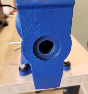
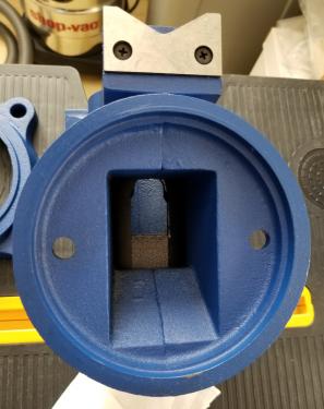
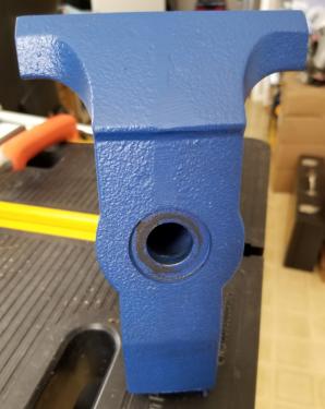
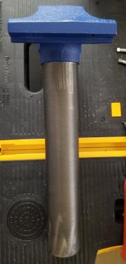
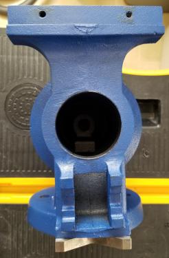
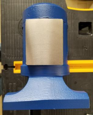
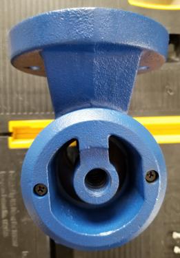
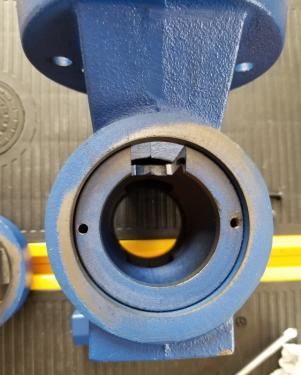
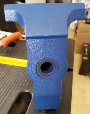
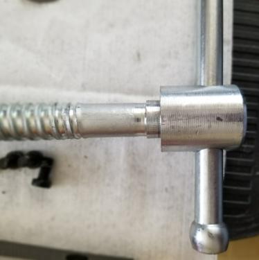
The collar on the screw is quite a loose fit in the hole. The hole is about .82" while the collar is about .75". I might attempt to make a ring that I can press onto the collar to take up some of the slack. Wait, I don't have a lathe yet!

The counterbore in the casting might be big enough to add a thrust bearing. Otherwise I could enlarge it on the mill. Wait, I don't have a mill yet!

I can't win.

Ed
Posts: 4,493
Threads: 187
Joined: Feb 2012
Location: Missouri, USA
The following 1 user Likes Highpower's post:
Clifford B. (05-05-2021)
(05-03-2021, 03:11 PM)EdK Wrote: ![[Image: attachment.php?thumbnail=16982]](http://www.metalworkingfun.com/attachment.php?thumbnail=16982)
I like this.
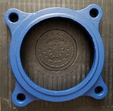
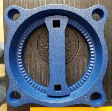
One of the things I dislike about my cheap bench vise are the slots in the base that allow the vise to swivel. The carriage bolts always slip and allow the vise body to spin when you are trying to bend something while parallel to the vice jaws. I have to hammer on the T handled nuts to get them to stop slipping. One of these days the carriage bolts are going to blow right through those slots. Those locking notches on yours look like the hot ticket.

I have to say that is probably the
cleanest Chinese casting I have ever seen! Wow. I agree with you on replacing all the hardware though. I know we've all been
there before.
Willie
Posts: 8,888
Threads: 320
Joined: Feb 2012
Location: Arizona/Minnesota
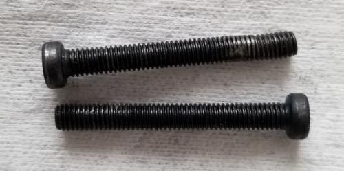
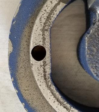
Well I found out why that screw was bent. The clearance hole didn't line up with the threaded hole and they just got it started and powered it in. To fix it I drilled the clearance hole with a drill bit 1/16" larger than the existing hole. It was getting close to the edge so I attacked it with a file to elongate the clearance hole. That did the trick.
I got the new hardware from McMaster yesterday and got that installed. The hardware that came with it was Phillips drive which I don't like for this application so I got socket head cap screws as replacements.
Ed
Posts: 8,888
Threads: 320
Joined: Feb 2012
Location: Arizona/Minnesota
The following 3 users Like EdK's post:
arvidj (06-14-2021), Highpower (06-15-2021), Vinny (06-15-2021)
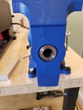
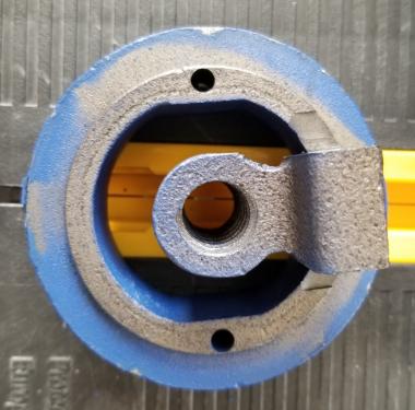
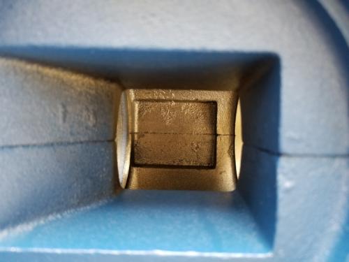
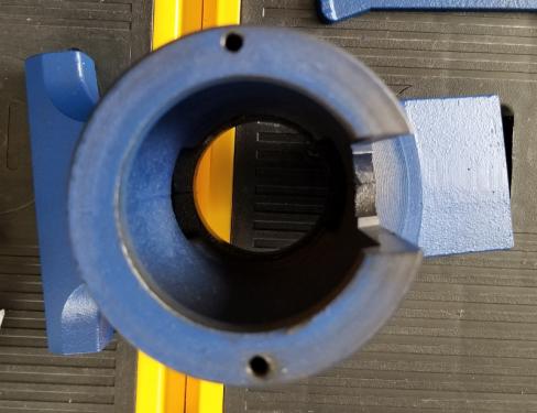
A forum member made me a brass bushing to take up some of the slop between the vise screw and the movable jaw. It worked for a while but eventually worked itself loose and fell inside the casting. He made it to my drawing but I gave him bad dimensions. I wanted a press fit into the hole but my dimension on the drawing wasn't quite correct.
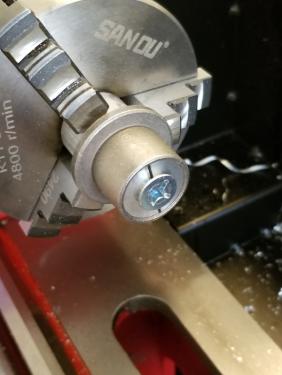
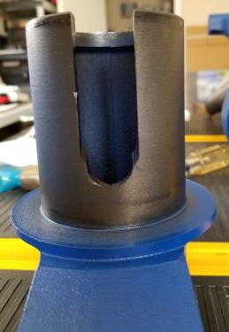
I found a bronze flanged bushing in my box of miscellaneous stuff and got lucky. The ID was .75" which is close enough to 19mm to work. The OD was .875" and needed to be turned down to .821" to fit the hole in the movable jaw. I made a mandrel planning on making the bushing a snug press fit on it so I could machine it using light cuts. I shouldn't have taken that last bit off of the OD of the mandrel.

So I went with plan B and drilled and tapped the mandrel 1/4-20 and countersunk the hole for a flat head screw. Then I cut a slit down the middle to basically make an expanding mandrel. Worked well and I got the bushing OD turned down to withing .0005" of my target. I then had to face off about .035" from the flange in order for the castle nut to line up with the hole for the cotter pin without the vise screw being too hard to turn, it needs some slack.
Ed
