Posts: 432
Threads: 27
Joined: Feb 2016
Location: Woodstock:GA
The following 2 users Like pepi's post:
TomG (03-18-2018), f350ca (03-18-2018)
03-18-2018, 08:34 AM
(This post was last modified: 03-18-2018, 08:43 AM by pepi.)
Keeping true to the KISS theory and being a hobby machinist. I look for ways to make set up, easier and more repeatable.
I stumbled across this tool hight set up gauge, and yesterday it showed its true value. Seems most have a problem (boots) using a parting tool.
Not so much a feed problem but the tool too work piece center. Most notable when moving the tool in or back to keep from hitting the chuck. Tool block holder has a ramp and an angle that changes the tool hight when moved.
This guy takes out the guess work & turns the set up time too 5 mins, I will explain the first picture the others self explanatory.
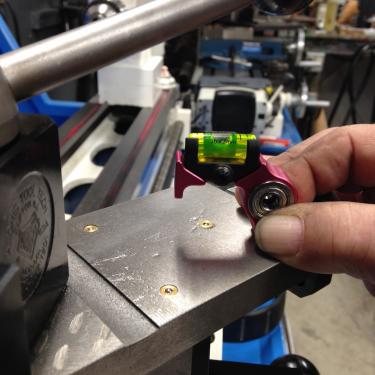
Setting the tool... set the base on the cross slide, note bubble. There is button screw that will allow the level to move, and center the bubble.
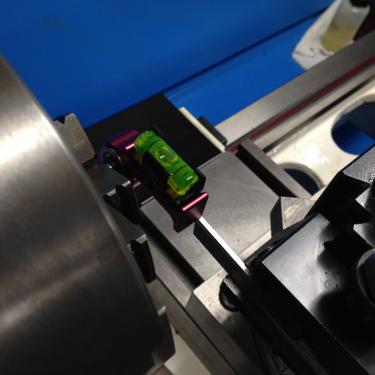
once set it's a no brainier ...
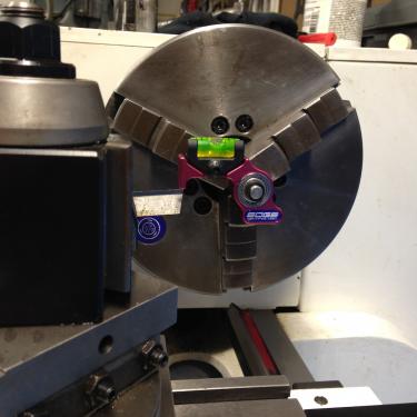
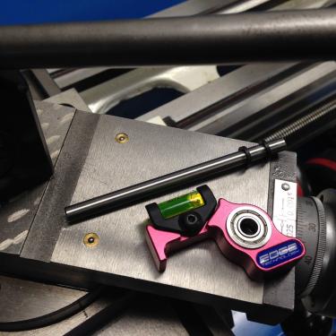
Button screw seen better here, adjust bubble as the indicator for the tool and cross slide
There are three version of this, one does not have the feature to adjust the level, the outer does some trick that frankly I did not see a use for me. The one pictured was the middle priced and does what I need it to do
Greg
Magazines have issues, everything else has problems
Posts: 3,799
Threads: 184
Joined: Jun 2012
Location: Farmington Hills, Michigan
This would make a fun little project. It would even be more useful if a way could be found to mount it on an already chucked part.
Tom
Posts: 3
Threads: 0
Joined: Mar 2018
Location: USA
Now this looks like a real helpful tool for every diy machinist :-) 
Posts: 275
Threads: 12
Joined: Mar 2012
Location: Nebraska, USA
(03-18-2018, 09:27 AM)TomG Wrote: This would make a fun little project. It would even be more useful if a way could be found to mount it on an already chucked part.
Tom
Pardon the quick "paint" drawing but a person could make a larger bracket that could fit around any round stock held in the lathe. Something like this...
![[Image: setter.png]](http://www.arcaneiron.com/machines/setter.png)
Ugly but hopefully gets the point across.
FWIW
-Ron
11" South Bend lathe - Wells-Index 860C mill - 16" Queen City Shaper
Posts: 215
Threads: 22
Joined: Jul 2017
Location: Eureka, CA, USA
03-18-2018, 06:51 PM
(This post was last modified: 03-18-2018, 06:53 PM by randyc.)
(03-18-2018, 09:27 AM)TomG Wrote: ........ It would even be more useful if a way could be found to mount it on an already chucked part.
Tom
Absolutely and Tom's idea should be fairly simple to implement, dunno why it wasn't included in the original design. The side opposite the "indicating" tip could look like a lathe dog or even a vee block with a spring-loaded clamp. This is a crude example but maybe something along the lines of an electronic guitar tuner but with the leveling bubble:
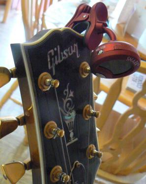
Not to be nit picky and it IS an ingenious little device but isn't it a solution looking for a problem ?
Seems like it would take longer to set it up than using the traditional vertical machinist's scale method, taking a trial facing cut then adjusting the height of the parting blade to shave off the "tit" - maybe thirty seconds work ? I suppose if one has forgotten to set the parting blade previously and cannot take a few mils off the face to check blade height this would be pretty handy ...
Maybe I'm missing something - it sure wouldn't be the first time 
P.S. Tom beat me to it !!!
Posts: 3,799
Threads: 184
Joined: Jun 2012
Location: Farmington Hills, Michigan
The following 1 user Likes TomG's post:
EdK (03-19-2018)
(03-18-2018, 06:51 PM)randyc Wrote: (03-18-2018, 09:27 AM)TomG Wrote: ........ It would even be more useful if a way could be found to mount it on an already chucked part.
Tom
Absolutely and Tom's idea should be fairly simple to implement, dunno why it wasn't included in the original design. The side opposite the "indicating" tip could look like a lathe dog or even a vee block with a spring-loaded clamp. This is a crude example but maybe something along the lines of an electronic guitar tuner but with the leveling bubble:
Not to be nit picky and it IS an ingenious little device but isn't it a solution looking for a problem ?
Seems like it would take longer to set it up than using the traditional vertical machinist's scale method, taking a trial facing cut then adjusting the height of the parting blade to shave off the "tit" - maybe thirty seconds work ? I suppose if one has forgotten to set the parting blade previously and cannot take a few mils off the face to check blade height this would be pretty handy ...
Maybe I'm missing something - it sure wouldn't be the first time 
P.S. Tom beat me to it !!!
There are a lot of gimmicky products like this on the market that really do take longer to implement than they are worth, but this one comes closer than most to actually being useful. I don't use the scale method because I don't care for the damage it does to the scale. The other tried and true method is to use a center in the tailstock, but that requires that a center actually be in the tailstock. I think if this tool was kept within arms reach of the lathe, it would get used, at least in my shop.
Looking at Ron's sketch, the clamping mechanism isn't even necessary. The tool can be held against the part with one hand and the tool height dialed in with the other. I'm building one. 
Tom
![[Image: TomsTechLogo-Profile.png]](http://tomstechniques.com/wp-content/uploads/2013/11/TomsTechLogo-Profile.png)
Posts: 275
Threads: 12
Joined: Mar 2012
Location: Nebraska, USA
03-18-2018, 08:17 PM
(This post was last modified: 03-18-2018, 08:18 PM by ScrapMetal.)
(03-18-2018, 07:13 PM)TomG Wrote: There are a lot of gimmicky products like this on the market that really do take longer to implement than they are worth, but this one comes closer than most to actually being useful. I don't use the scale method because I don't care for the damage it does to the scale. The other tried and true method is to use a center in the tailstock, but that requires that a center actually be in the tailstock. I think if this tool was kept within arms reach of the lathe, it would get used, at least in my shop.
Looking at Ron's sketch, the clamping mechanism isn't even necessary. The tool can be held against the part with one hand and the tool height dialed in with the other. I'm building one. 
Tom
Cool! I'll be interested to see your take on the design. When I get the time I'll be doing one for myself as well.
-Ron
11" South Bend lathe - Wells-Index 860C mill - 16" Queen City Shaper
Posts: 3,003
Threads: 51
Joined: Apr 2012
Location: Ontario
The following 1 user Likes f350ca's post:
randyc (03-19-2018)
Sorry, not a great picture, but thats my setter off to the left.
![[Image: UOJ67mf231NvLoCZdFDGD9Hfnl27QR4vUTRHiOgY...11-h609-no]](https://lh3.googleusercontent.com/UOJ67mf231NvLoCZdFDGD9Hfnl27QR4vUTRHiOgYKZkaeJlHH-vWHkzK1MAjCkVSRKvsOC5gSxOCen8NA-yY7kMWiwI-Rcnd6bJvIAnzUsVWgyLi69rTrYy2zD9CnDh0JvEeuUl_ujOv3aBzMXKTcDsKc73SdkailVu_58tnTgdrGX7Ht788ydVKK2BNmAden21yZl_KIdlEFZAqMbzZxKWkI14EZEXXiuPyvMN9gYgJ8QwGaAvBlapxVQV7uzkncw-akXty1h7YIPa6WH-S5lGgfetdF7CZfeC02JrI9GkWaO27C56iTfrw38n35BYfhRp5v-QE1mvMVSWcr_kafIzAVPguT0I694ZwkzuXLS3CcxYiMpSJz35C8tblVTJ9uJI5EIGGnaAbNp86sdDXMpyY_0iK1grAeLbh83wRV5eQLO1itWm3sX23Q9iXMjIgEcdbe3m6B028Lu0rFaquanVGuhkHOZ6eXYa7bwFn3fnHcGuAhA1AJFt7eicUlWFM0-cEobailOmK0LguzjxoS8qYf9Z3phc4mflOC2-AjSua5K81NEcrmdqsWv3cCxqUM258E3vm7Uh0-ayHWgooX4s2BGq-tTAu-ehnAfM=w811-h609-no)
There's a thin cap you can't see in the photo. You can use it above the tool, or level the tool with the surface you see. The lower joint swings over to give the height off the top of the compound. They're all held to the base with a bolt through an offset hole.
Free advice is worth exactly what you payed for it.
Greg
Posts: 536
Threads: 39
Joined: Jan 2013
Location: Kelowna, BC, Canada
Tom, you could set a couple of rare earth magnets into the inside of the V to help hold the rig in place on ferrous metals. The adjustable vial is still a good idea, just to get it 'level' relative to your lathe bed.
Mike
If you can't get one, make one.
Hawkeye, proud to be a member of MetalworkingFun Forum since Jan 2013.
Posts: 3,799
Threads: 184
Joined: Jun 2012
Location: Farmington Hills, Michigan
Thought about that Mike, but the location would depend on the part diameter. The adjustable level part is cool, but not really necessary. The lathe would have to be WAY out of level for it to matter. I'll probably use the KISS approach and leave that off. I would make it out of tool steel and harden it for durability. Probably add a few pockets as well to keep it light.
Tom
|


![[Image: TomsTechLogo-Profile.png]](http://tomstechniques.com/wp-content/uploads/2013/11/TomsTechLogo-Profile.png)

![[Image: setter.png]](http://www.arcaneiron.com/machines/setter.png)

