07-05-2012, 10:30 PM
(This post was last modified: 07-05-2012, 11:11 PM by henryarnold.)
Today I worked on the brackets to connect the Y Axis scale pickup to the carriage. The bracket mounts on the carriage area I milled yesterday and bolts to two threaded holes on the scale pickup.
I made the bracket from 2 pieces of angle aluminum. the larger one is 3/16" thick and connects to the carriage. The other piece is 1/16" and thick and cradles the pickup. These two pieces form an "S" shape that goes between the carriage and the pickup.
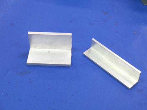
I slotted the pieces so that they can be adjusted once mounted on the lathe. There needs to be the ability to adjust the pickup position in relation to the scale in 2 directions. The first direction is how close the pickup is to the scale and the second direction is the vertical planarity to the scale.
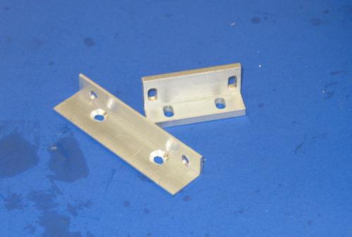
Once I completed the milling of slots and holes, I assembled the 2 pieces. The thinner long piece bolts to the scale and has countersunk screws that connect it to the other bracket which is slotted so that the offset can be adjusted. The other bracket bolts to the carriage through 2 more slotted holes which provide the adjustment of the pickup distance to the scale. This photo shows the completed assembly upside down so that you can see the slots that are used to bolt to the carriage and the countersunk screw area where the scale pickup rests.
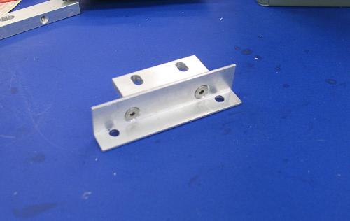
I installed the bracket assembly and then checked the clearance between the pickup and scale. For my scale, this distance needs to be 0.050"-0.060". The adjustment for this is where the bracket connects to the carriage. The vertical planarity of the pickup to the scale is adjusted using the flat head screws that connect the parts of the "S" shape which expands or contracts the offset from the carriage to where the bracket connects to the pickup.
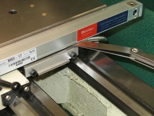
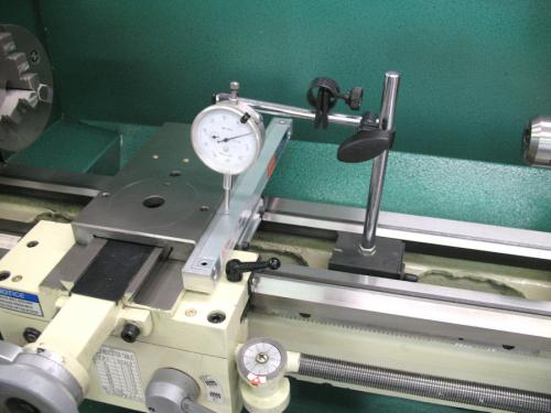
I also rechecked the horizontal planarity of the scale to the travel of the cross slide. I also rechecked my pickup clearance at each end of the cross slide travel.
I made the bracket from 2 pieces of angle aluminum. the larger one is 3/16" thick and connects to the carriage. The other piece is 1/16" and thick and cradles the pickup. These two pieces form an "S" shape that goes between the carriage and the pickup.
I slotted the pieces so that they can be adjusted once mounted on the lathe. There needs to be the ability to adjust the pickup position in relation to the scale in 2 directions. The first direction is how close the pickup is to the scale and the second direction is the vertical planarity to the scale.
Once I completed the milling of slots and holes, I assembled the 2 pieces. The thinner long piece bolts to the scale and has countersunk screws that connect it to the other bracket which is slotted so that the offset can be adjusted. The other bracket bolts to the carriage through 2 more slotted holes which provide the adjustment of the pickup distance to the scale. This photo shows the completed assembly upside down so that you can see the slots that are used to bolt to the carriage and the countersunk screw area where the scale pickup rests.
I installed the bracket assembly and then checked the clearance between the pickup and scale. For my scale, this distance needs to be 0.050"-0.060". The adjustment for this is where the bracket connects to the carriage. The vertical planarity of the pickup to the scale is adjusted using the flat head screws that connect the parts of the "S" shape which expands or contracts the offset from the carriage to where the bracket connects to the pickup.
I also rechecked the horizontal planarity of the scale to the travel of the cross slide. I also rechecked my pickup clearance at each end of the cross slide travel.
henryarnold, proud to be a member of MetalworkingFun Forum since Apr 2012.


