11-03-2017, 10:14 PM
Another important part(s) to be made is the workholder. I wrote earlier that from now on I was going to think things out and actually “design” the item and I sure tried, ha-ha-ha. I sketched out three or four variations of a work holder. All of them were plausible IF the application involved larger work.
Even though it wasn’t yet clear in my mind what the work holder should look like, for sure it needs to fit the dovetailed platform of the ball joint. I’d envisioned the workholding platform to be a sliding, low-friction, manually reciprocating work holder. That may change, however.
Still lacking a design for the work holder, I thought that I’d go ahead and make a dovetailed platform that could be tailored once the final design evolved. The blank was ½ inch (12.5 mm) thick, low carbon hot rolled steel plate (nasty stuff). After sawing and milling to finish length and width, taking a 10 mil cut on either side to remove scale, I cut the dovetails.
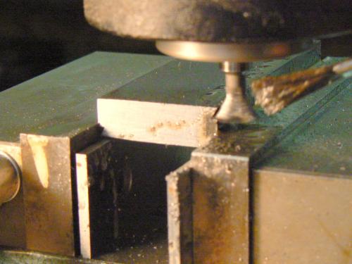
I reasoned that it would be a good idea to cut dovetails on both top and bottom sides of a long workholder. I thought that this would give me several areas to custom machine for individual grinding fixtures. Before dovetailing both sides, I tried a single side for fit, sliding friction and tightness of lock-up. The fit being satisfactory, I completed the remaining dovetails.
At this point, I had an idea. I like toolmakers vises and own a couple of them, one full-size version and a small (one inch- 25 mm) duplicate that is useful for working on small, delicate parts. This is the large one, the smaller vise is approximately a one-quarter size version of this one.

Most, if not all, of the parts that I would likely grind would be small and the little vise seemed a good way to hold them. Note that there is a definite disadvantage to using this style of vise. The design is intended to apply both clamping pressure and a downward load to prevent the movable jaw from lifting.
However the angular clamping increases friction as the vise is tightened and as the angle changes, eventually zero clamping pressure on the workpiece results, all of the pressure becomes vertical. Obviously in certain circumstances this is of serious concern.
These devices were originally intended for surface grinders and other light operations that exert small cutting loads. They are, in my personal opinion, not suitable for normal milling operations although people use them for this purpose, apparently with satisfaction.
A vise with insufficient clamping pressure can, at best, ruin the workpiece and, at worst, cause physical harm !
However for my application, this type of workholder would seem to be ideal. After all, it is a grinding operation, for which the vise was intended, and the amount of material being removed is very small.
Mounting the little vise on the end of the platform rather than on top of the platform, as I’d originally envisioned, seemed like the best idea. Happily the Asian manufacturer had thoughtfully provided tapped holes on both sides of the vise. This was fortunate since the entire vise is hardened and, for me, tapping holes would not have been possible.
The holes looked like #8-32 but the #8 screw was too large. I tried a #6-32 screw but it was too small. I tried all of my metric taps in the range of the major diameter. No luck. But the #6-32 seemed, by feel, to be the correct pitch. An uneasy thought occurred to me and it turned out to be correct ....
Who knew that there was a #7-32 screw and WHY would a Chinese designer choose to use that thread ?
Googling #7-32 produced a surprising number of hits. Apparently many people have experienced this problem in various forms. One person suggested a major diameter of .150 inches for making a #7 screw. This is plausible since it is the mean of #6 and #8 major diameters. (I'm sure that the dimensions are thoroughly documented in "Machinery's Handbook".)
My first thought was to modify an #8-32 screw by first turning down to .150 (~ 4 mm) major diameter and then single pointing the existing 32 pitch threads a bit deeper, to the required minor diameter. Well, that worked but it wasn’t pretty. I could have tried the same thing on a #10-32 thread but frankly, holding the head of screws in a workholder not designed for the purpose is clumsy and insecure.
I decided to make a couple of screws from oil hardening tool steel so that they could be hardened. Further – and for no good reason other than I like them – I decided to make the screws in the configuration of square headed half-dog screws. These are universally used on older lathes for clamping purposes and I like old machinery so …...
There happened to be a short length of ½ inch (12.5 mm) diameter O-1 lying in the chip pan under the horizontal bandsaw – perfect. The length was WAY long enough to accommodate the full collet length, preventing springing and bell-mouthing.
Since I needed only two screws, it seemed convenient to make them from both ends of the rod, turning the rod end-for-end and duplicating each operation, rather than handling two small parts. I first turned the major diameters for the #7 threads and then transferred to another lathe:
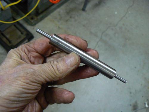
The Emco-Maier "Compact Eight" lathe uses loose threading gears so it was easier to use my Sheldon EXL-56 lathe with QC gear box to set up the 1/32 inch lead. The Emco, because of its compact, short, solid structure and its collet system, is better for making small parts that don’t exceed eighteen inches (46 cm). It is simply easier and more handy to use than a larger machine.
Little parts are often a PITA to machine (and to de-burr) and this operation was a typical problem ! Because of the short distance between collet and tailstock center, for single-pointing these threads the old lantern and Armstrong tool holder was my first choice.
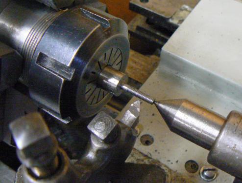
After single-pointing both ends of the rod, I secured it in a 5-C collet held in a four-sided collet block then installed it in the milling vise. I milled all four sides to the ¼ inch square head that I’d decided was in proportion with the #7 threads. Then removed the rod from the collet, turned it around and milled the other end identically.
Note that I’m still working with the four inch long piece of O-1, not two little pieces, so workholding has not been a problem. I put the rod back in the Emco-Maier lathe, turned a groove under the square head (to remove milling tool marks) and parted the screws from the rod.
Now two small pieces must be held in the lathe and the first unforeseen problem was encountered. Although ER-40 collets are claimed to accommodate 1/8 to 1 inch (3 to 25 mm) with no gaps in coverage, this was not the fact. The .150 (~4 mm) major diameter of the screws could not be forced into a 1/8 collet nor could a 3/16 collet be tightened securely enough on the screws.
I was at a total loss at this point and almost replaced the collet system in the Emco with a four inch (100 mm) 4-jaw chuck. But that also would have been a PITA to use with these small parts. I had another thought: how about securing an Albrecht 3-jaw drill chuck in a collet and using the Albrecht to hold the screws ?
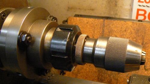
Happily the Albrecht runout was minimal enough to hold the threaded lengths while I finished the remaining operations on the heads of the two screws. If I did this again, I would definitely center drill and support the heads of the screws. (If center drilling was a problem, then a small spud, backed up by a live center would be my choice.)
These are the finished and heat-treated screws:

Next chore was to make a mounting device for the toolmaker’s vise, to securely attach it to the vee-grooved work platform. A remnant of the piece of hot rolled steel was still in the vise of the horizontal saw, so a piece of that would end up mounting the vise. I squared the stock to dimensions and drilled/counterbored mounting holes for the vise.

This is a routine operation so one may wonder why I even included the photo. The reason is that the workpiece is held only on one side of the mill vise - the vise will tilt slightly, causing uneven wear, so I've inserted a scrap piece of steel, the same thickness as the workpiece, on the right side of the vise jaws to equalize the load on them.
After cleaning the parts, I silver-soldered the "mounting bar" to the dovetailed work platform. This simple process requires only a couple of minutes and makes a fairly strong joint. In the photo, there is no silver observable at the joint of the parts. My hands are very shaky and I didn't trust myself to make a clean join by feeding the silver into the joint.
I made a long loop of solder, placed it on the anvil of my vise and flattened it well with a hammer. Applying flux to both parts first, I placed the flattened solder between them. Standing the dovetailed part vertically with the corresponding part on top, both parts were heated with a rosebud O/A torch until the joint was made. This technique eliminated the problems that would have resulted from my unstable hands.

The work holder finally ended up like this - the little vise of course is attached with the #7 square head screws. A scale can be established from the size of the eye glasses. It's a compact little assembly.
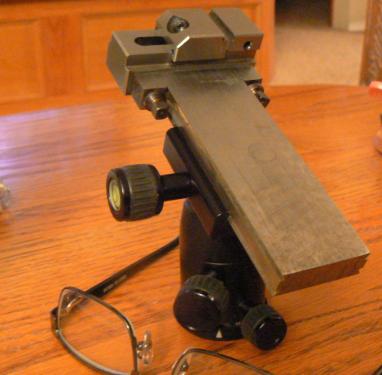
But I became dissatisfied at this point for some of the following reasons:
Even though it wasn’t yet clear in my mind what the work holder should look like, for sure it needs to fit the dovetailed platform of the ball joint. I’d envisioned the workholding platform to be a sliding, low-friction, manually reciprocating work holder. That may change, however.
Still lacking a design for the work holder, I thought that I’d go ahead and make a dovetailed platform that could be tailored once the final design evolved. The blank was ½ inch (12.5 mm) thick, low carbon hot rolled steel plate (nasty stuff). After sawing and milling to finish length and width, taking a 10 mil cut on either side to remove scale, I cut the dovetails.
I reasoned that it would be a good idea to cut dovetails on both top and bottom sides of a long workholder. I thought that this would give me several areas to custom machine for individual grinding fixtures. Before dovetailing both sides, I tried a single side for fit, sliding friction and tightness of lock-up. The fit being satisfactory, I completed the remaining dovetails.
At this point, I had an idea. I like toolmakers vises and own a couple of them, one full-size version and a small (one inch- 25 mm) duplicate that is useful for working on small, delicate parts. This is the large one, the smaller vise is approximately a one-quarter size version of this one.
Most, if not all, of the parts that I would likely grind would be small and the little vise seemed a good way to hold them. Note that there is a definite disadvantage to using this style of vise. The design is intended to apply both clamping pressure and a downward load to prevent the movable jaw from lifting.
However the angular clamping increases friction as the vise is tightened and as the angle changes, eventually zero clamping pressure on the workpiece results, all of the pressure becomes vertical. Obviously in certain circumstances this is of serious concern.
These devices were originally intended for surface grinders and other light operations that exert small cutting loads. They are, in my personal opinion, not suitable for normal milling operations although people use them for this purpose, apparently with satisfaction.
A vise with insufficient clamping pressure can, at best, ruin the workpiece and, at worst, cause physical harm !
However for my application, this type of workholder would seem to be ideal. After all, it is a grinding operation, for which the vise was intended, and the amount of material being removed is very small.
Mounting the little vise on the end of the platform rather than on top of the platform, as I’d originally envisioned, seemed like the best idea. Happily the Asian manufacturer had thoughtfully provided tapped holes on both sides of the vise. This was fortunate since the entire vise is hardened and, for me, tapping holes would not have been possible.
The holes looked like #8-32 but the #8 screw was too large. I tried a #6-32 screw but it was too small. I tried all of my metric taps in the range of the major diameter. No luck. But the #6-32 seemed, by feel, to be the correct pitch. An uneasy thought occurred to me and it turned out to be correct ....
Who knew that there was a #7-32 screw and WHY would a Chinese designer choose to use that thread ?
Googling #7-32 produced a surprising number of hits. Apparently many people have experienced this problem in various forms. One person suggested a major diameter of .150 inches for making a #7 screw. This is plausible since it is the mean of #6 and #8 major diameters. (I'm sure that the dimensions are thoroughly documented in "Machinery's Handbook".)
My first thought was to modify an #8-32 screw by first turning down to .150 (~ 4 mm) major diameter and then single pointing the existing 32 pitch threads a bit deeper, to the required minor diameter. Well, that worked but it wasn’t pretty. I could have tried the same thing on a #10-32 thread but frankly, holding the head of screws in a workholder not designed for the purpose is clumsy and insecure.
I decided to make a couple of screws from oil hardening tool steel so that they could be hardened. Further – and for no good reason other than I like them – I decided to make the screws in the configuration of square headed half-dog screws. These are universally used on older lathes for clamping purposes and I like old machinery so …...
There happened to be a short length of ½ inch (12.5 mm) diameter O-1 lying in the chip pan under the horizontal bandsaw – perfect. The length was WAY long enough to accommodate the full collet length, preventing springing and bell-mouthing.
Since I needed only two screws, it seemed convenient to make them from both ends of the rod, turning the rod end-for-end and duplicating each operation, rather than handling two small parts. I first turned the major diameters for the #7 threads and then transferred to another lathe:
The Emco-Maier "Compact Eight" lathe uses loose threading gears so it was easier to use my Sheldon EXL-56 lathe with QC gear box to set up the 1/32 inch lead. The Emco, because of its compact, short, solid structure and its collet system, is better for making small parts that don’t exceed eighteen inches (46 cm). It is simply easier and more handy to use than a larger machine.
Little parts are often a PITA to machine (and to de-burr) and this operation was a typical problem ! Because of the short distance between collet and tailstock center, for single-pointing these threads the old lantern and Armstrong tool holder was my first choice.
Neither a 4-way nor a QC would fit in this small space with enough freedom and travel to cut the threads. I suppose that a long cutting tool like a boring bar with a sixty degree cutter could work, allowing the tool holder to be distanced from the work. But why monkey around making a new tool when the trusty lantern and the Armstrong holder has worked for a century ?
By the way, this is just one reason for using the old system: the ability to “sneak” into restrictive areas. But there are many other reasons and I think that most of us would benefit from having some of this (quite) inexpensive tooling stored (along with the face plate and lathe dogs, LOL).
Note the use of a dead center - a live center would take up more of the already limited work envelope available. A live center is definitely not needed anyway. Most single pointing is performed in back gear and there is little stress on the dead center, just give it a drop of oil occasionally.
After single-pointing both ends of the rod, I secured it in a 5-C collet held in a four-sided collet block then installed it in the milling vise. I milled all four sides to the ¼ inch square head that I’d decided was in proportion with the #7 threads. Then removed the rod from the collet, turned it around and milled the other end identically.
Note that I’m still working with the four inch long piece of O-1, not two little pieces, so workholding has not been a problem. I put the rod back in the Emco-Maier lathe, turned a groove under the square head (to remove milling tool marks) and parted the screws from the rod.
Now two small pieces must be held in the lathe and the first unforeseen problem was encountered. Although ER-40 collets are claimed to accommodate 1/8 to 1 inch (3 to 25 mm) with no gaps in coverage, this was not the fact. The .150 (~4 mm) major diameter of the screws could not be forced into a 1/8 collet nor could a 3/16 collet be tightened securely enough on the screws.
I was at a total loss at this point and almost replaced the collet system in the Emco with a four inch (100 mm) 4-jaw chuck. But that also would have been a PITA to use with these small parts. I had another thought: how about securing an Albrecht 3-jaw drill chuck in a collet and using the Albrecht to hold the screws ?
Happily the Albrecht runout was minimal enough to hold the threaded lengths while I finished the remaining operations on the heads of the two screws. If I did this again, I would definitely center drill and support the heads of the screws. (If center drilling was a problem, then a small spud, backed up by a live center would be my choice.)
These are the finished and heat-treated screws:
Next chore was to make a mounting device for the toolmaker’s vise, to securely attach it to the vee-grooved work platform. A remnant of the piece of hot rolled steel was still in the vise of the horizontal saw, so a piece of that would end up mounting the vise. I squared the stock to dimensions and drilled/counterbored mounting holes for the vise.
This is a routine operation so one may wonder why I even included the photo. The reason is that the workpiece is held only on one side of the mill vise - the vise will tilt slightly, causing uneven wear, so I've inserted a scrap piece of steel, the same thickness as the workpiece, on the right side of the vise jaws to equalize the load on them.
After cleaning the parts, I silver-soldered the "mounting bar" to the dovetailed work platform. This simple process requires only a couple of minutes and makes a fairly strong joint. In the photo, there is no silver observable at the joint of the parts. My hands are very shaky and I didn't trust myself to make a clean join by feeding the silver into the joint.
I made a long loop of solder, placed it on the anvil of my vise and flattened it well with a hammer. Applying flux to both parts first, I placed the flattened solder between them. Standing the dovetailed part vertically with the corresponding part on top, both parts were heated with a rosebud O/A torch until the joint was made. This technique eliminated the problems that would have resulted from my unstable hands.
The work holder finally ended up like this - the little vise of course is attached with the #7 square head screws. A scale can be established from the size of the eye glasses. It's a compact little assembly.
But I became dissatisfied at this point for some of the following reasons:
(1) In the same length of time required to make these screws, I could have made a hex cutter for my rotary broach (http://www.metalworkingfun.com/showthrea...ary+broach) and made two "proper" #7-32 hex keyed socket head cap screws. I would have two serviceable screws and also have another broaching tool, which is always desirable.
(2) There was so much repetitive work (e.g. single pointing the threads, milling the squares) that I had a lot of time to think about my design and I concluded that it doesn't need to be this complex, I had a simpler idea that doesn't include the square head screws.
The new concept will require three #7-32 FLAT HEAD screws, ha-ha-ha, so I have to do this single-pointing chore again. Since I spend only an hour or so a day on this project, the next episode will probably be at least a week away.
Cheers !


