08-30-2017, 04:49 PM
This morning, I had an appointment with an ophthalmologist to discuss cataract removal in my left eye. As the doc was jotting down his notes and I was admiring the precision optical equipment, my eyes (well, one eye, ha-ha-ha) lit on this little mechanism.
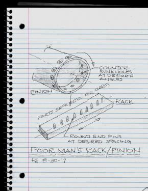
Ever had a need for a custom pair of gears or rack/pinion ? Maybe you could use a non-standard number of teeth or strange diameter, etcetera, for an uncritical, slow speed application. Here’s an idea that would let you make a pair of “gears” in an hour or so:

(Click on the sketch to see an enlargement)
Perhaps this is a well-known method of approximating gearing but it was new to me and I’ll keep the idea in mind for possible future application ! (The only thing similar to this that I can recall is a movie projector film transport, but the projector drive wheel teeth are shaped more like a gear.)
The sketch shows the two parts disengaged and separated, just for clarity. Also, I neglected to note on the sketch that the pins are tapered as well as rounded.
The length of the pins and the taper are chosen to properly engage the counter-sunk holes in the mating part. A CAD drawing would easily determine the correct configuration.
I thought that this was a very ingenious way of optimizing cost versus function and I hope that the designer got a raise for the idea !
Ever had a need for a custom pair of gears or rack/pinion ? Maybe you could use a non-standard number of teeth or strange diameter, etcetera, for an uncritical, slow speed application. Here’s an idea that would let you make a pair of “gears” in an hour or so:
(Click on the sketch to see an enlargement)
Perhaps this is a well-known method of approximating gearing but it was new to me and I’ll keep the idea in mind for possible future application ! (The only thing similar to this that I can recall is a movie projector film transport, but the projector drive wheel teeth are shaped more like a gear.)
The sketch shows the two parts disengaged and separated, just for clarity. Also, I neglected to note on the sketch that the pins are tapered as well as rounded.
The length of the pins and the taper are chosen to properly engage the counter-sunk holes in the mating part. A CAD drawing would easily determine the correct configuration.
I thought that this was a very ingenious way of optimizing cost versus function and I hope that the designer got a raise for the idea !


