02-12-2016, 12:21 AM
While my mill is apart I wanted to look into something that has been bugging me for a couple of years now. Once in awhile my quill would stick when down feeding using the fine-feed wheel. Most often when I tried to come down a few thousandths to a specific depth. The quill movement would start to get stiff, then suddenly jump down much farther than I wanted to go. The outside of the quill is clean and smooth, as is the bore in the head that it rides in. This happened to me before - years ago, before I had installed my power drawbar. Adding some grease to the splines on the spindle made the problem go away.... temporarily.
With the head apart I was able to get a good look at the spindle splines and found several nicks and burrs on the upper portion of the spindle.
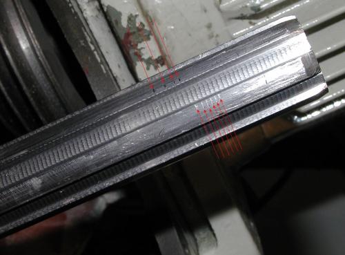
The only thing I could think of that would cause this would be the driven spindle shaft hitting a sharp edge inside the belt drive tube/shaft where the mating driving splines are. Even though the ends of the splines are chamfered they do still have an "edge" to them. And my mill has always had a slight rattle sound to it when its running because there is some backlash between the splines. But put a heavy cut on a flycutter.... ho-lee-cow!
I cleaned up all the parts and then smoothed out the nicks/burrs on the spindle splines. Holding the drive tube over the spindle I found I could rock it back and forth a bit - top to bottom. Looking further I see that the drive spindle (tube) only has splines in in the center portion of the tube. The bottom of the tube has an oversize counter bore in it for the first 2 inches, then there is 2 inches of splines above that. The top 3-1/2 inches of the tube is also counter bored. I measured the parts and found there is a difference of .070" between the OD of the splines and the ID of the counter bores in the tube.
I'm thinking that would account for the nicks in the splines if the driven spindle is being whipped around inside the tube and flexing because of too much clearance. Bending the spindle would cause the shaft to dig in to the edges of the splines in the center of the tube. Maybe?
At any rate I turned some sleeves out of some graphite filled bronze rod (lots of expensive swarf there!) to take out some of the excessive clearance and hopefully hold things in line better. The sleeves are .030" wall thickness so that leaves me with .010" clearance (total) for the splines to run in. At least I hope so.
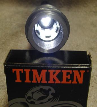
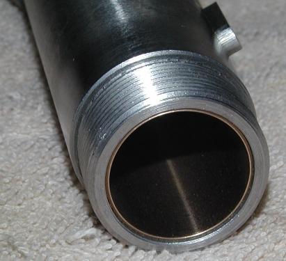

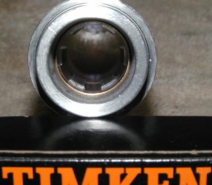
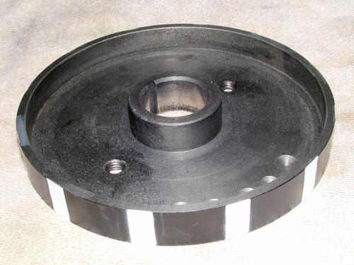
The spindle brake drum was slightly modified by cutting some flats around the OD to serve as an encoder wheel for a MachTach display. While the brake drum was off I also drilled and tapped it for 2 Helicoil inserts. This way if I ever need to touch-up the paint on my "encoder" I can use a stud-type gear puller to get it off instead of having to pull the entire drive spindle out to get at it.
Got the drive spindle assy back together with new (sealed ) bearings, ready to go back into the mill. Still need to work on a mount for the IR speed sensor though. Not much room to work with.

With the head apart I was able to get a good look at the spindle splines and found several nicks and burrs on the upper portion of the spindle.
The only thing I could think of that would cause this would be the driven spindle shaft hitting a sharp edge inside the belt drive tube/shaft where the mating driving splines are. Even though the ends of the splines are chamfered they do still have an "edge" to them. And my mill has always had a slight rattle sound to it when its running because there is some backlash between the splines. But put a heavy cut on a flycutter.... ho-lee-cow!

I cleaned up all the parts and then smoothed out the nicks/burrs on the spindle splines. Holding the drive tube over the spindle I found I could rock it back and forth a bit - top to bottom. Looking further I see that the drive spindle (tube) only has splines in in the center portion of the tube. The bottom of the tube has an oversize counter bore in it for the first 2 inches, then there is 2 inches of splines above that. The top 3-1/2 inches of the tube is also counter bored. I measured the parts and found there is a difference of .070" between the OD of the splines and the ID of the counter bores in the tube.

I'm thinking that would account for the nicks in the splines if the driven spindle is being whipped around inside the tube and flexing because of too much clearance. Bending the spindle would cause the shaft to dig in to the edges of the splines in the center of the tube. Maybe?

At any rate I turned some sleeves out of some graphite filled bronze rod (lots of expensive swarf there!) to take out some of the excessive clearance and hopefully hold things in line better. The sleeves are .030" wall thickness so that leaves me with .010" clearance (total) for the splines to run in. At least I hope so.
The spindle brake drum was slightly modified by cutting some flats around the OD to serve as an encoder wheel for a MachTach display. While the brake drum was off I also drilled and tapped it for 2 Helicoil inserts. This way if I ever need to touch-up the paint on my "encoder" I can use a stud-type gear puller to get it off instead of having to pull the entire drive spindle out to get at it.
Got the drive spindle assy back together with new (sealed
 ) bearings, ready to go back into the mill. Still need to work on a mount for the IR speed sensor though. Not much room to work with.
Willie


