11-23-2015, 09:15 PM
Sorry about the delay in progress. I can only really work on this project during the weekends. I hope to get some more work done this week as I have most of Thanksgiving week off.
After getting the bottom flattened out I mounted the body on my Mill. I lightly clamped down the piece with 3 toe clamps. I then put a wiggler/pointer in the mill spindle and indicated on the parting line running down the length. There isnt much else to use a reference other than the parting line in the casting. I also stuck a length of 1/2 pipe through the horizontal bore to help orient it with the mill table. After I was happy with it I tightened up on the clamps. I then set the X axis t o zero over the parting line track. Since this is cast iron I covered the mill table with 2 towels to help keep iron grit controlled.
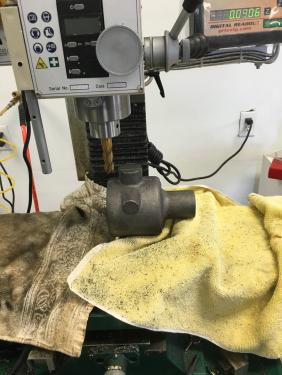
Once I was happy with the set up I started removing the lug at the top which had been used in the lathe chuck to flatten the bottom.
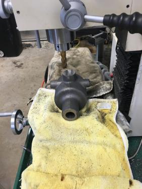
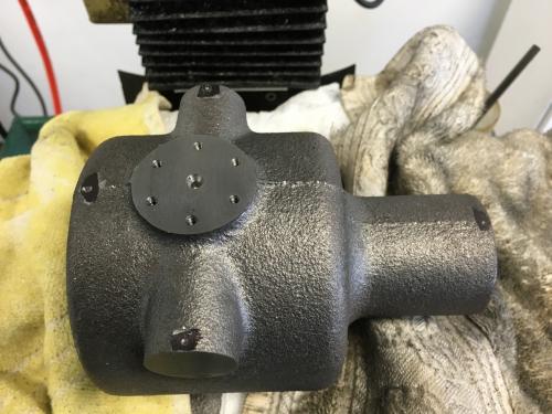
The height of the body is called out in the plans. After mowing the top off to just a few thousands left to go I took off the last bit with a fly cutter ( forgot to get a picture, sorry). With that done it was time to start thinking about establishing some additional references. The plans specify the distance from the horizontal shaft bore (far right side in the pictures) to the center line of the vertical shaft. The face of the horizontal bore had been sawn off, or was a very rough grind so I decided to start there. I vertical milled the face and then measured back to just milled surface horizontal surface. By eyeball it looked pretty centered. So I went back, found the vertical face with an edge finder and dialed in the distance to the bore. I now had 0 in X and 0 in Y established for the vertical shaft bore. Spot drilled the center and drilled/tapped the bolt circle.
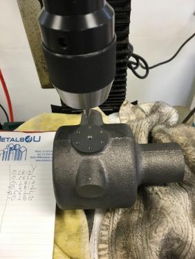
Next up was the 2 bosses running perpendicular to the parting line. These are for bolting on the arms which hold up the table. The plans call out the distance from the vertical bore to the vertical face of each boss. as you would expect they are equidistant from the center line. I loaded a 5/8 end mill, computed how much to take off and cleaned up the bosses.
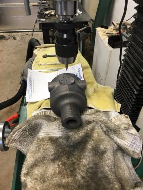
Lastly I milled off a little flat area on top of just finished arm bosses, at the top of the horizontal shaft bore and on its opposite end. I then marked the flats with a black sharpie and then used a spot drill to mark 0 axis in X and Y witness marks. These will come in handy later.
After getting the bottom flattened out I mounted the body on my Mill. I lightly clamped down the piece with 3 toe clamps. I then put a wiggler/pointer in the mill spindle and indicated on the parting line running down the length. There isnt much else to use a reference other than the parting line in the casting. I also stuck a length of 1/2 pipe through the horizontal bore to help orient it with the mill table. After I was happy with it I tightened up on the clamps. I then set the X axis t o zero over the parting line track. Since this is cast iron I covered the mill table with 2 towels to help keep iron grit controlled.
Once I was happy with the set up I started removing the lug at the top which had been used in the lathe chuck to flatten the bottom.
The height of the body is called out in the plans. After mowing the top off to just a few thousands left to go I took off the last bit with a fly cutter ( forgot to get a picture, sorry). With that done it was time to start thinking about establishing some additional references. The plans specify the distance from the horizontal shaft bore (far right side in the pictures) to the center line of the vertical shaft. The face of the horizontal bore had been sawn off, or was a very rough grind so I decided to start there. I vertical milled the face and then measured back to just milled surface horizontal surface. By eyeball it looked pretty centered. So I went back, found the vertical face with an edge finder and dialed in the distance to the bore. I now had 0 in X and 0 in Y established for the vertical shaft bore. Spot drilled the center and drilled/tapped the bolt circle.
Next up was the 2 bosses running perpendicular to the parting line. These are for bolting on the arms which hold up the table. The plans call out the distance from the vertical bore to the vertical face of each boss. as you would expect they are equidistant from the center line. I loaded a 5/8 end mill, computed how much to take off and cleaned up the bosses.
Lastly I milled off a little flat area on top of just finished arm bosses, at the top of the horizontal shaft bore and on its opposite end. I then marked the flats with a black sharpie and then used a spot drill to mark 0 axis in X and Y witness marks. These will come in handy later.
If it's crazy but it works, it's not crazy.


