05-24-2015, 06:49 AM
Thanks Ken - I wasn't aware that they were the same manufacturer. One thing I did note was that the concentric rings are marked in inch diameters.
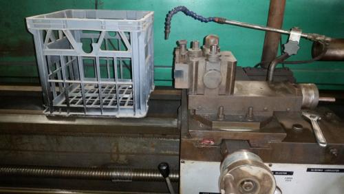
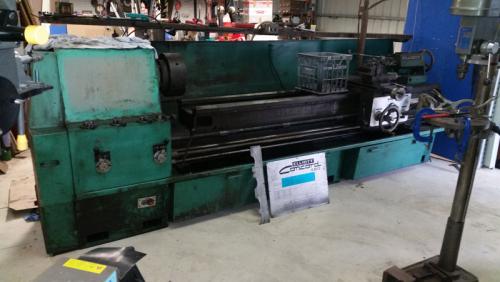
Thanks Pete - here are a couple of pictures with a good old Aussie milk crate for reference! Also, in the holder is a 1" shank negative rake profiling tool gifted to me by Wrustle.
The clutches were actually a little more difficult to adjust that the instructions on the cover and in the manual lead me to initially believe. First the drawing wasn't all that flash and the manual didn't even have a drawing! Second, you need to have very little hands or very long fingers and third, you should grow an additional hand as well.
You have to slide the knurled ring away from the clutch pack whilst navigating the copper oil line and the shaft in front. Once the knurled ring has moved, you set the gap to 0.041" with a feeler gauge (or two if you don't have the correct one). I only had bent end ones here, which complicated things. My straight ones are in my other shop.
Reverse clutch ready for adjustment
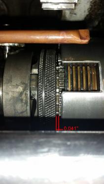
Forward clutch adjusted
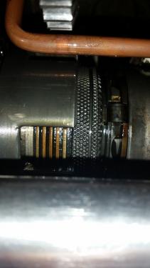
For some reason, I couldn't understand why the brake clutch pack was so difficult to adjust. I couldn't even slide the knurled ring. Then it suddenly dawned on me. The instructions said to disengage the clutch, so when I adjusted the fwd/rev clutches, I had the spindle lever in the off position. I left it in this position, not thinking (obviously), as the off position engages the brake Once the lever was put into fwd, the brake clutch was much easier to adjust. Of note, the copper tubes ensure that the clutches are oiled continuously during use.
Normally, the next step would have been to put the rear and top covers back on and try the spindle. However, my gasket forming goo is in my other workshop (with my straight feeler gauges), so I couldn't power her up. However, the lever now remains in the reverse position, which it didn't do initially. There also seems to be a more defined disengagement of the fwd/rev positions. Of course, this could mean nothing under power...
Next, I turned my head to the cross slide and compound slide. Looking at the rear of the cross slide, I think I have found where the taper attachment fits:
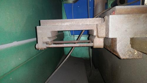
Looking ahead - I'm not sure how best to mount a DRO slide here, as the side of the cross slide is machined at an angle. I have read that rear toolposts and other attachments were available for these lathes, and wonder if they were dovetailed, as both the front and rear sides are the same.
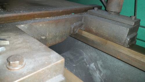
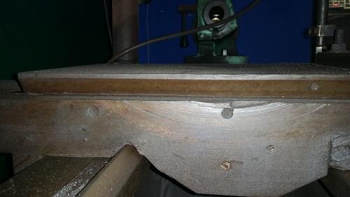
As the above pictures shows, there has been at least one decent crash on this lathe... I will have to modify the crane mounting position to fit the scale to the rear of the cross slide. I'm not even going to consider mounding it on the front, given that I have a following steady.
I have been throwing some of the fasteners and other small items into the tumbler today. Last in was the OIL nipple on the front of the cross slide. Why do people see these and assume they are for grease
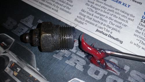
Oh well, at least none of the handles have been broken on this, unlike my mill.
Thanks Pete - here are a couple of pictures with a good old Aussie milk crate for reference! Also, in the holder is a 1" shank negative rake profiling tool gifted to me by Wrustle.
The clutches were actually a little more difficult to adjust that the instructions on the cover and in the manual lead me to initially believe. First the drawing wasn't all that flash and the manual didn't even have a drawing! Second, you need to have very little hands or very long fingers and third, you should grow an additional hand as well.
You have to slide the knurled ring away from the clutch pack whilst navigating the copper oil line and the shaft in front. Once the knurled ring has moved, you set the gap to 0.041" with a feeler gauge (or two if you don't have the correct one). I only had bent end ones here, which complicated things. My straight ones are in my other shop.
Reverse clutch ready for adjustment
Forward clutch adjusted
For some reason, I couldn't understand why the brake clutch pack was so difficult to adjust. I couldn't even slide the knurled ring. Then it suddenly dawned on me. The instructions said to disengage the clutch, so when I adjusted the fwd/rev clutches, I had the spindle lever in the off position. I left it in this position, not thinking (obviously), as the off position engages the brake
 Once the lever was put into fwd, the brake clutch was much easier to adjust. Of note, the copper tubes ensure that the clutches are oiled continuously during use.
Normally, the next step would have been to put the rear and top covers back on and try the spindle. However, my gasket forming goo is in my other workshop (with my straight feeler gauges), so I couldn't power her up. However, the lever now remains in the reverse position, which it didn't do initially. There also seems to be a more defined disengagement of the fwd/rev positions. Of course, this could mean nothing under power...
Next, I turned my head to the cross slide and compound slide. Looking at the rear of the cross slide, I think I have found where the taper attachment fits:
Looking ahead - I'm not sure how best to mount a DRO slide here, as the side of the cross slide is machined at an angle. I have read that rear toolposts and other attachments were available for these lathes, and wonder if they were dovetailed, as both the front and rear sides are the same.
As the above pictures shows, there has been at least one decent crash on this lathe... I will have to modify the crane mounting position to fit the scale to the rear of the cross slide. I'm not even going to consider mounding it on the front, given that I have a following steady.
I have been throwing some of the fasteners and other small items into the tumbler today. Last in was the OIL nipple on the front of the cross slide. Why do people see these and assume they are for grease

Oh well, at least none of the handles have been broken on this, unlike my mill.
Hunting American dentists since 2015.


