04-27-2015, 07:25 AM
O K time for a bit more,
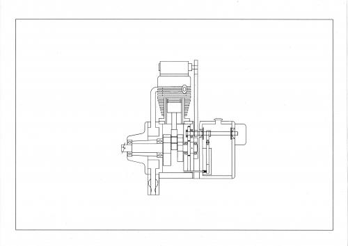
First I must tell you that on the drawing the accessory shaft is shown connected to number one cylinder cam drive.
this is only to make the drawing simpler to do, in fact the drives are taken from cylinders two and five.
After a lot of head scratching I have made the oil tank integral with the crank case this allows the two oil pumps to be inside the tank and driven by eccentrics on the accessory shafts and the distributor mounted at the rear of the tank.
The carb is mounted under the nose piece feeding an annular chamber. then out to the cylinder's
Still a lot of work to do but it's coming together.

Brian.
First I must tell you that on the drawing the accessory shaft is shown connected to number one cylinder cam drive.
this is only to make the drawing simpler to do, in fact the drives are taken from cylinders two and five.
After a lot of head scratching I have made the oil tank integral with the crank case this allows the two oil pumps to be inside the tank and driven by eccentrics on the accessory shafts and the distributor mounted at the rear of the tank.
The carb is mounted under the nose piece feeding an annular chamber. then out to the cylinder's
Still a lot of work to do but it's coming together.
Brian.


