05-11-2012, 11:36 AM
(This post was last modified: 05-11-2012, 11:46 AM by henryarnold.)
This post will show the installation of the gear shafts and speed selector forks. As stated earlier, I decided to do my shaft installation in the bottom of the head. Some people have done the assembly on the top half. Either way results in some bearings being pressed into place by screwing the lid down.
The shafts drop in easily on my mill. The bottom bearing hole receives the shaft bearings with just a little pressure. Install the motor shaft first and then the 1st Intermediate shaft. They need to go in this order because the gears overlap the bearing on the previous shaft. While installing the 1st Intermediate shaft, line up the right selector fork and shoe. Look at the photos if you're not sure where the shoe rides.
I already installed my speed selector rods and loosely attached the forks that carry the selector shoes. My shoes had burrs around the holes so I used a countersink to remove the burr.
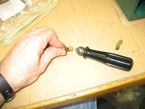
Although the gearbox will be bathed in oil, I thought it wouldn't hurt to put a little white grease on the shoe before installation.
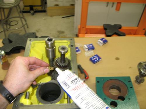
Here's the right shoe installed.
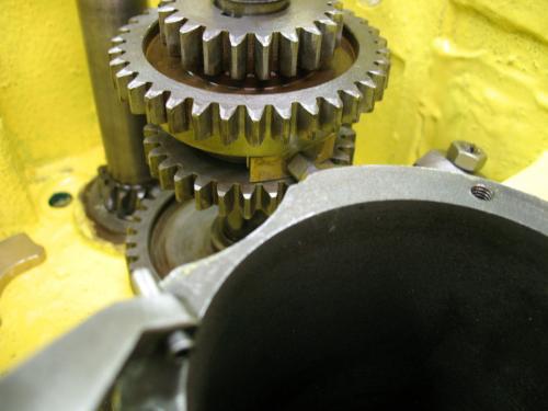
Install the 2nd Intermediate Shaft while lining up the left hand selector fork and shoe.
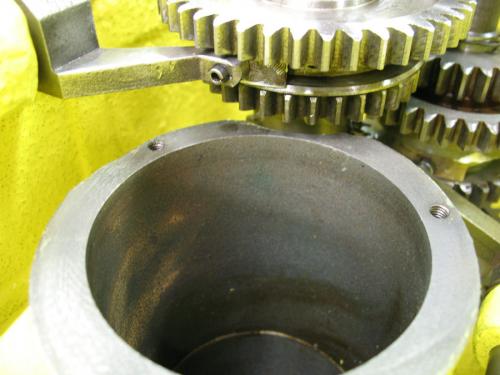
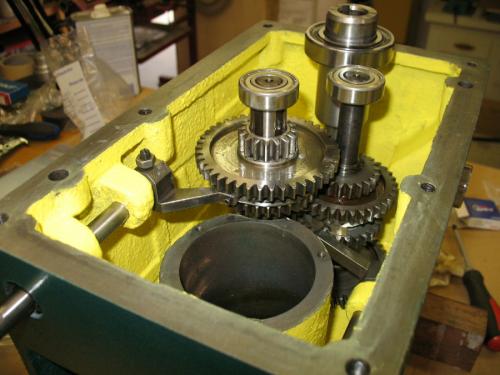
This photo shows all three shafts that will be installed in the bottom half of the head. The selector forks need to be adjusted. I noted when I was disassembling the head that the forks were not screwed onto the shafts tight. There was a small amount of compliance determined by the set screw and retainer nut. During reassembly, I tightened the set screw all the way and then backed it off about a 1/4 turn and then tightened the nut. I'm not sure why the compliance is needed but it seems like the forks were designed to be slightly loose so I put them back they way I found them.
You may recall that I said earlier that the spindle shaft must be mounted in the top half of the head. There are no bearings for this shaft in the bottom half. I'll show the installation of the spindle shaft in a later post. In this photo you'll notice that the top bearing on the 2nd Intermediate shaft is installed. I had to remove this bearing and install it in the top half because it conflicted with a large gear on the spindle shaft.
The shafts drop in easily on my mill. The bottom bearing hole receives the shaft bearings with just a little pressure. Install the motor shaft first and then the 1st Intermediate shaft. They need to go in this order because the gears overlap the bearing on the previous shaft. While installing the 1st Intermediate shaft, line up the right selector fork and shoe. Look at the photos if you're not sure where the shoe rides.
I already installed my speed selector rods and loosely attached the forks that carry the selector shoes. My shoes had burrs around the holes so I used a countersink to remove the burr.
Although the gearbox will be bathed in oil, I thought it wouldn't hurt to put a little white grease on the shoe before installation.
Here's the right shoe installed.
Install the 2nd Intermediate Shaft while lining up the left hand selector fork and shoe.
This photo shows all three shafts that will be installed in the bottom half of the head. The selector forks need to be adjusted. I noted when I was disassembling the head that the forks were not screwed onto the shafts tight. There was a small amount of compliance determined by the set screw and retainer nut. During reassembly, I tightened the set screw all the way and then backed it off about a 1/4 turn and then tightened the nut. I'm not sure why the compliance is needed but it seems like the forks were designed to be slightly loose so I put them back they way I found them.
You may recall that I said earlier that the spindle shaft must be mounted in the top half of the head. There are no bearings for this shaft in the bottom half. I'll show the installation of the spindle shaft in a later post. In this photo you'll notice that the top bearing on the 2nd Intermediate shaft is installed. I had to remove this bearing and install it in the top half because it conflicted with a large gear on the spindle shaft.
henryarnold, proud to be a member of MetalworkingFun Forum since Apr 2012.


