OK - I spent some time today trying to get some half decent pics. Here is what I wound up with:
This is the part in question. This is the hub that allows the quill feed to be used with a handwheel.

Here is the 'exploded diagram' showing the detent ball, spring and set screw.

Here we are looking from 9 o'clock through to 3 o'clock (referenced to the 1st pic).

This is the shaft that it mates with. The large hole is suppose to line up with this 5.15mm hole, which has a 5mm detent ball that locates the fwd/neutral/rev for the quill feed.

On the opposite side of the shaft is the 5mm key that indexes the handwheel hub. With the hub indexed by the key, the hole for the detent ball, spring and lock screw don't line up with the hole on the shaft (this is the 2D drawing that confused you ).
).

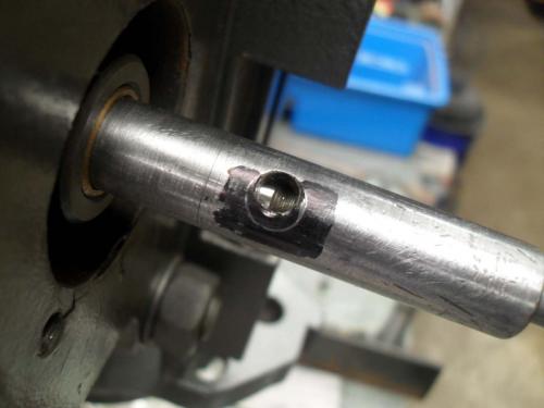
To make things a little easier, I put some sharpie ink on the shaft and then scribed the inside of the hole on the hub. Here you can see how far off the hole is.

This is the part in question. This is the hub that allows the quill feed to be used with a handwheel.
Here is the 'exploded diagram' showing the detent ball, spring and set screw.
Here we are looking from 9 o'clock through to 3 o'clock (referenced to the 1st pic).
This is the shaft that it mates with. The large hole is suppose to line up with this 5.15mm hole, which has a 5mm detent ball that locates the fwd/neutral/rev for the quill feed.
On the opposite side of the shaft is the 5mm key that indexes the handwheel hub. With the hub indexed by the key, the hole for the detent ball, spring and lock screw don't line up with the hole on the shaft (this is the 2D drawing that confused you
 ).
).To make things a little easier, I put some sharpie ink on the shaft and then scribed the inside of the hole on the hub. Here you can see how far off the hole is.
Hunting American dentists since 2015.


