You may recall that I mentioned that I met someone from the far North of Western Australia, who has a similar lathe. Well he was kind enough to not only send me pictures of his lathe (and specifically the parts on mine that are missing) but he also dismantled some of it, so I could better understand how it works.
A few pics of his lathe:
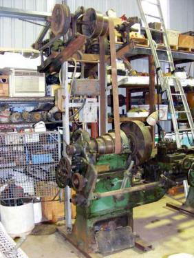
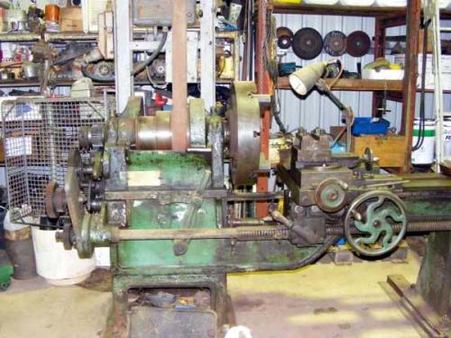
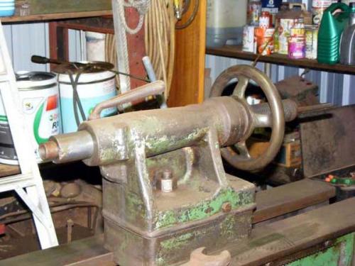
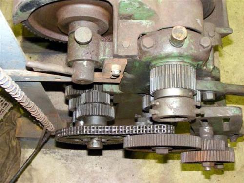
On these lathes, the feed is driven from a shaft that runs on the rear of the lathe. This shaft is chain driven off of the tumbler output.
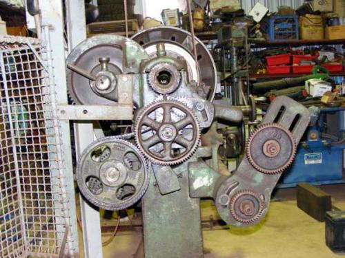
In the picture above, it actually looks like the change gear is meshed with the driven sprocket. However, the two do not line up and there is no interference, as you will see below:
The chain drives a three gear cluster, which mates with three independent gears on the feed shaft.
The gear cluster/independent gears viewed from behind
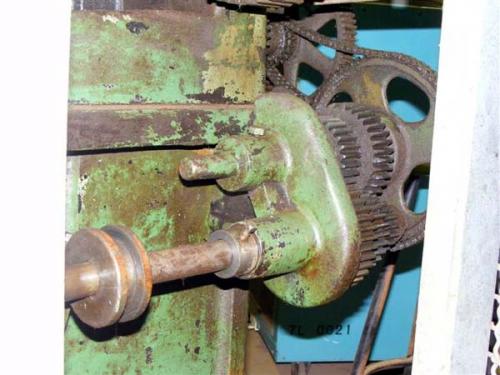
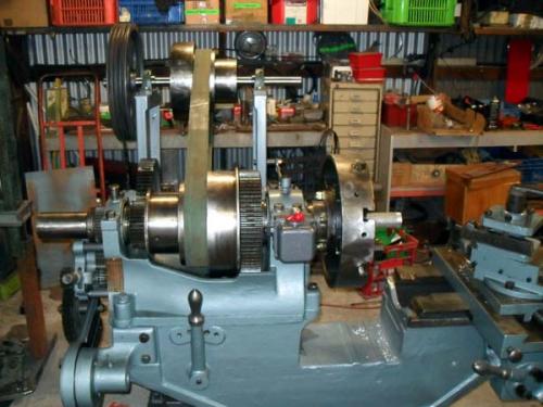
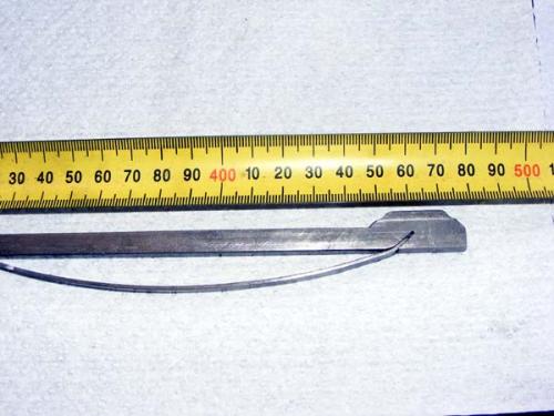
The large lever on the front of the headstock (visible in the second pic in this post) moves a collar, which in turn, moves a spring loaded key. There is a bevelled spacer between each of the independent feed shaft gears, which pushes the key down, allowing it to slide from one gear to the next. So, the five detent positions on the lever correspond to High / Neutral / Medium / Neutral / Low.
The feed rate change lever on my lathe
The cluster removed from its shaft and one of the independent gears removed to show the bevelled spacer and the key
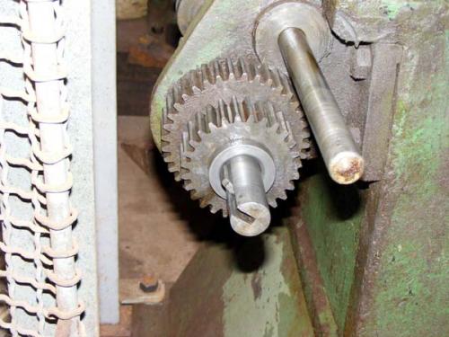
The spring loaded key and one of the bevelled spacers
 Old lathe2 001.jpg (Size: 30.25 KB / Downloads: 247)
Close up of the spring
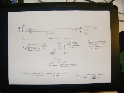
The technical stuff (Ed will probably replicate this in CAD)
A few pics of his lathe:
On these lathes, the feed is driven from a shaft that runs on the rear of the lathe. This shaft is chain driven off of the tumbler output.
In the picture above, it actually looks like the change gear is meshed with the driven sprocket. However, the two do not line up and there is no interference, as you will see below:
The chain drives a three gear cluster, which mates with three independent gears on the feed shaft.
The gear cluster/independent gears viewed from behind
The large lever on the front of the headstock (visible in the second pic in this post) moves a collar, which in turn, moves a spring loaded key. There is a bevelled spacer between each of the independent feed shaft gears, which pushes the key down, allowing it to slide from one gear to the next. So, the five detent positions on the lever correspond to High / Neutral / Medium / Neutral / Low.
The feed rate change lever on my lathe
The cluster removed from its shaft and one of the independent gears removed to show the bevelled spacer and the key
The spring loaded key and one of the bevelled spacers
 Old lathe2 001.jpg (Size: 30.25 KB / Downloads: 247)
Close up of the spring
The technical stuff (Ed will probably replicate this in CAD)
Hunting American dentists since 2015.


