I actually missed one post, which should have preceded the one on the QCTP. 
Once the lathe was operational I attacked scraps of metal and slowly tightened gibs and made adjustments that needed to be made. The compound slide only has three adjustment screws and if you want to work close to the chuck you often have one of these hanging out in the breeze. So I decided it would be worth adding a couple extra screws.
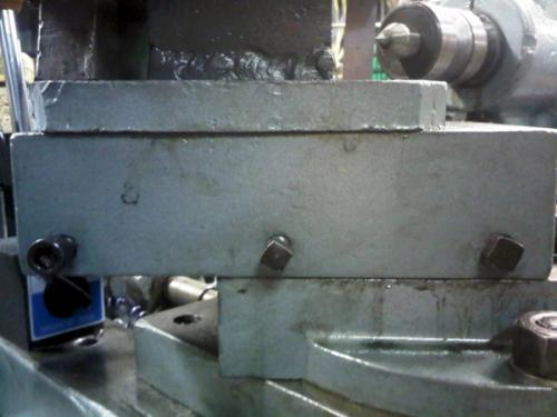
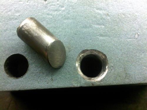
One of the holes had stripped, so I decided to drill them all out to 1/2" and braze in some steel plugs, which I would then drill and tap for the original 7/16" bolts. The top of the pins were bevelled, as was the mouth of the hole (I actually went a little more aggressive on the metal removal that these pics show).
Plug and hole prepared
All plugs brazed into place and drilled for tapping
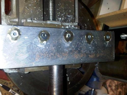
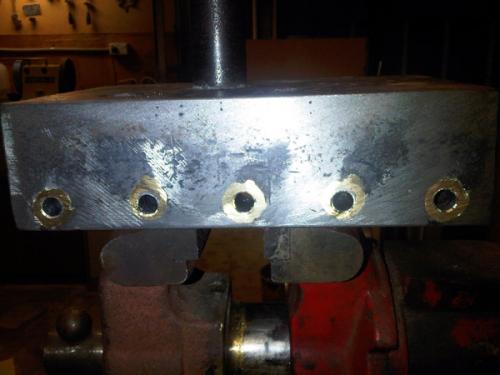
A mismatch of bolts but all done!
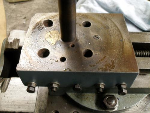
The centre one doubles as a lock. I drilled a hole through this bolt and pushed some nylon line trimmer cord through this hole and then trimmed it flush to the major diameter. This is the male version of a Nylock nut and will not rattle loose.
Just out of interest - here is a picture of the compound nut, which is cast iron.
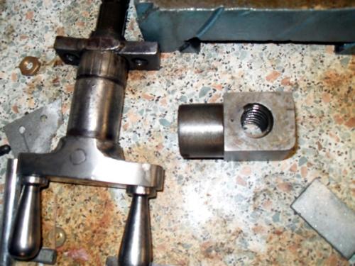
At the same time I also removed the cross slide screw, as it was bent. I didn't notice this before, as the front retaining housing was also loose and masked the bend. The issue was in the front portion of the screw and given the damage to the handwheel, I'm guessing someone clipped it with a forklift. I pressed almost all of the bend out and it is much better now.
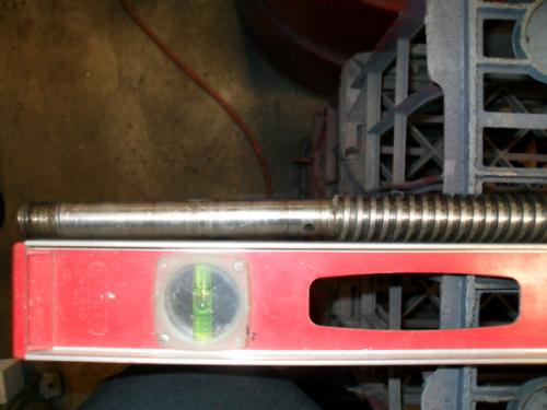
The bend is slight but annoying when cranking the handle
Here is the nut (still on the), screw, front bush and handwheel.
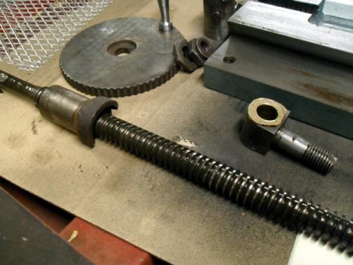
Here is the front gib adjustment screw on the cross slide.
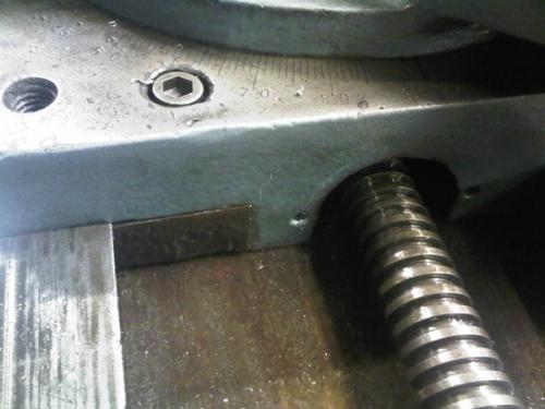
There was always some play in the cross slide which was more than just backlash. I finally figured out that the hole visible in the shaft (where it is sitting on top of the level) is for a pin, which retains the thrust bearing. Once I place a washer and pin in place the cross slide behaved much better.

Once the lathe was operational I attacked scraps of metal and slowly tightened gibs and made adjustments that needed to be made. The compound slide only has three adjustment screws and if you want to work close to the chuck you often have one of these hanging out in the breeze. So I decided it would be worth adding a couple extra screws.
One of the holes had stripped, so I decided to drill them all out to 1/2" and braze in some steel plugs, which I would then drill and tap for the original 7/16" bolts. The top of the pins were bevelled, as was the mouth of the hole (I actually went a little more aggressive on the metal removal that these pics show).
Plug and hole prepared
All plugs brazed into place and drilled for tapping
A mismatch of bolts but all done!
The centre one doubles as a lock. I drilled a hole through this bolt and pushed some nylon line trimmer cord through this hole and then trimmed it flush to the major diameter. This is the male version of a Nylock nut and will not rattle loose.
Just out of interest - here is a picture of the compound nut, which is cast iron.
At the same time I also removed the cross slide screw, as it was bent. I didn't notice this before, as the front retaining housing was also loose and masked the bend. The issue was in the front portion of the screw and given the damage to the handwheel, I'm guessing someone clipped it with a forklift. I pressed almost all of the bend out and it is much better now.
The bend is slight but annoying when cranking the handle
Here is the nut (still on the), screw, front bush and handwheel.
Here is the front gib adjustment screw on the cross slide.
There was always some play in the cross slide which was more than just backlash. I finally figured out that the hole visible in the shaft (where it is sitting on top of the level) is for a pin, which retains the thrust bearing. Once I place a washer and pin in place the cross slide behaved much better.
Hunting American dentists since 2015.


