Posts: 1,827
Threads: 51
Joined: Apr 2012
Location: Oklahoma
thanks for the compliment, I'm working on it not in a big hurry moneys tight and I'm at a point now that I need to buy some things like the bearings that I need to fit that round part that is on the end of the plate which will have the lead screw running thru it.
hopefully in a couple days I can get the parts that I need
dallen, proud to be a member of MetalworkingFun Forum since Apr 2012.
If life seems normal, your not going fast enough! 
Posts: 1,827
Threads: 51
Joined: Apr 2012
Location: Oklahoma
snagged a power supply today off of a friend that said he had a few extras and wanted to know if I could use a 12 volt 36 amp supply, my first response was when you want me there to pick it up.
so one more problem solved, but another problem has reared its ugly head.
anyway my mill has a different size column then the plans I have been sort of following and I find out this after noon that I am going to have to do some serious parts making or start from scratch on mounting the drive setup that I have already made. The big challenge is with keeping the parts that I have already made and doing a fix that looks like it was the first choice and not the last one.
Pictures to follow as I work on the problem.
dallen, proud to be a member of MetalworkingFun Forum since Apr 2012.
If life seems normal, your not going fast enough! 
Posts: 4,683
Threads: 93
Joined: Feb 2012
Location: Perth, Australia
That is a decent power supply. Nice score!
Hunting American dentists since 2015.
Posts: 1,827
Threads: 51
Joined: Apr 2012
Location: Oklahoma
sorry for not posting sooner but been working on several things lately, but back to the mini mill.
heres a photo of what I am trying to do.

this is basically the same as what I had in the other photos except that it is made to mount to the back of the column. with some support under the mount on top of the column instead of all the mount strength being in the top. I'm not sure about some of the measurements due to not having things like the bearings or the timing cogs (cogs on order) going to look into bearings tomorrow here local.
I have room in the slide plate if I need to to cut the two slots about a half inch longer which then I can turn it around and mount it the other direction which will help with belt length. the motor that is shown on the mount is not the one that will actually be used I still have to purchase a motor for the Z Axis, and the spacers/stands that the motor is mounted on top of will probably have to be cut shorter.
dallen, proud to be a member of MetalworkingFun Forum since Apr 2012.
If life seems normal, your not going fast enough! 
Posts: 1,827
Threads: 51
Joined: Apr 2012
Location: Oklahoma
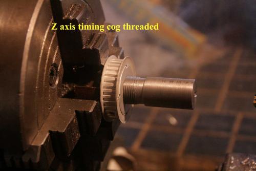
I'm slow but was lucky in that I had received my drive parts (two cogs and a XL120 belt) the other day, so since it was way to hot today to work on the back door ( project that I started yesterday) I decided to do the threads for the Acme Nut that will have to screw into the cog.
I used a thread gauge that I made way back when I change the chinese screws out on the table to insure that the nut hopefully will fit when I get it.

dallen, proud to be a member of MetalworkingFun Forum since Apr 2012.
If life seems normal, your not going fast enough! 
Posts: 1,827
Threads: 51
Joined: Apr 2012
Location: Oklahoma
08-18-2012, 07:55 PM
(This post was last modified: 08-19-2012, 02:44 PM by dallen.)
new motor mount almost complete

this photo shows how much I will have to trim the Z axis mount for the spindle motor to clear.

from the front

still trying to decide if I want to cut the mount plate off or leave it

dallen, proud to be a member of MetalworkingFun Forum since Apr 2012.
If life seems normal, your not going fast enough! 
Posts: 4,513
Threads: 139
Joined: Feb 2012
Location: Kempton Park. South Africa


 so far


