Posts: 537
Threads: 15
Joined: Jun 2012
Location: Cambridge, England
(07-18-2012, 06:11 AM)stevec Wrote: Rick, is there any point/or possibilty of making up some form of "quick connect" to your carriage and use it to pull/push your tailstock to/from the head stock (I'm assuming that's what you meant by employing the power feed unit).
Also, (careful I'm rambling on here) I have seen some large older lathes with a hand crank on the tailstock to advance/retract it, I think it utilized the carriage rack.
Hello Steve,
A hook up to the carriage is possible but using it to drill with is problematic as unless the clamp is locked the tailstock isn't securely located and of course if it is locked it can't move with the carriage.
Big old lathes and just big lathes in general sometimes have a rack gear for moving the tailstock into position before locking, given the weight of the tailstock the weight alone is enough to hold the tailstock down when drilling small holes as a result this drive could be used but in most cases, it's ratio isn't ideal anyway, some big lathes also have a two speed gearbox on their tailstock quill, which makes it easier to drill big diameter holes, my Colchester is not one of these lathes.
Best Regards
Rick
Whatever it is, do it today, Tomorrow may not be an option and regret outlasts fatigue.
Posts: 537
Threads: 15
Joined: Jun 2012
Location: Cambridge, England
(07-18-2012, 05:55 AM)Bogstandard Wrote: Rick,
What you have to realise, the Z feed not only has to drill and bore the holes, ie, cutting metal, it also has to lift that very large casting under the table, the table itself with all the stuff hanging on it, RT, vice and of course two more power feeds as well. Guesstimated weight, 400 to 500 pounds. The whole machine weighs around a ton.
So unless you are drilling something like 6" diameter holes from a 1/4" centre hole, I think it could cope with your large tailstock.
I limited myself to 1.5" holes for drilling, over that, I then bore it out, purely because that is the size of my largest drill.
Hello John,
1.5" is a pretty normal sized hole for me with the largest I have drilled being 4" but I envisage that 2" will be about my limit from here on in. I have seen these types of feed units on z axes for a little while now but my limited experience with them wasn't great, being that most of my mills have been more "Industrial" I've had quite a few import mills over the years but only one with an "off the shelf" aftermarket feed unit, and lets just say it was less than reliable, and that was just on the x axis, so I thought with the z as you say lifting all that weight as well as drilling it just might be worth asking the question. Thanks for your opinion on the matter.
Best regards
Rick
Whatever it is, do it today, Tomorrow may not be an option and regret outlasts fatigue.
I acquired my Atlas MFB 4 weeks ago (ugly green one in the photo in new member section) and completely disassembled it, cleaned, replaced worn/damaged parts, painted and reassembled and here it is. It came with a rotary table, original indexer, adjustable angle plate, vise and lots of cutters and end mills for the very handy vertical head. I'm finishing up the final wiring but this mill is an awesome hobbyist machine. Glad to be a part of this forum.
One thing I need is some information on the small cover on the Y-axis marked M1-37B in the parts breakdown. I have an idea where and how it should look but a definite description would help a lot.
Posts: 11
Threads: 1
Joined: Jul 2012
Location: Warwickshire, UK
07-24-2012, 02:16 AM
(This post was last modified: 07-24-2012, 02:30 AM by lemelman.)
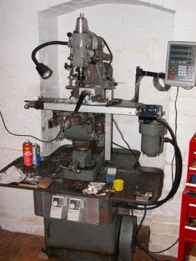
I'm in UK and here's my Centec 2B horizontal mill with a Mk3 vertical head. It's a robust small industrial machine; a full description can be found here http://http://www.lathes.co.uk/centec/index.html
It is unusual in that it has Int-30 spindles instead of the more common MT2.
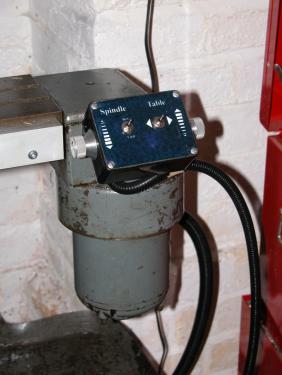
When I first got it, both motors (spindle and power feed) were 3-phase 480v, running from a home made single to 3-phase rotary converter, which was both noisy and clumsy to use, so I decided to convert to 240v VFD operation. Unfortunately, neither motor had the coil winding tails exposed, so I had to strip them down, burst the star-points, and create terminals for the new tails. The Mitsubishi VFDs are mounted below the swarf tray and angled upwards so that they can be seen by just glancing down. The little control box is mounted at the end of the table - speed via the knurled knobs on either side, and direction via the the toggle switches. Finger-tip control is very handy.
I also fitted a 3-axis Newall DRO, with the Microsyn encoders.
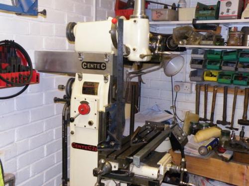
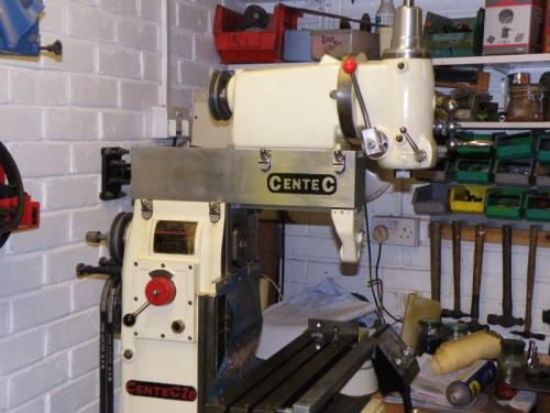
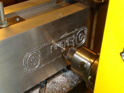
Since the Centec mills were originally designed for horizontal use, the vertical heads were an "after thought" and the maximum vertical space is a little compromised, so I made a couple of raising blocks - one for me and one for a friend. The horizontal over-arm and vertical head are attached to the column by a massive dovetail, but conversion between the modes is a hassle because of the weight of the VH. My raising blocks allow the VH to be left in place, and slid forward for horizontal mode, or back for vertical mode. I got a friend with a CNC mill to cut the Centec logo into the side of the raising blocks.
The grey m/c is my mill, the cream one, which shows the operation of the raising block, is my friend's, and the other photo shows the logo being cut.
lemelman, proud to be a member of MetalworkingFun since Jul 2012.
Posts: 8,863
Threads: 319
Joined: Feb 2012
Location: Arizona/Minnesota
Interesting little mill you've got there lemelman. 
Ed
Posts: 4,513
Threads: 139
Joined: Feb 2012
Location: Kempton Park. South Africa
Lemelman
A very nice robust mill you have there. 
Have you used it much ?

DaveH
Posts: 11
Threads: 1
Joined: Jul 2012
Location: Warwickshire, UK
(07-24-2012, 06:13 AM)DaveH Wrote: Have you used it much ?

DaveH
Hi Dave, yes I've used it lots.
Now that I've retired (from writing operating systems for an international computer company) I spend many hours in the workshop making things for disabled people.
I do voluntary work for a UK national charity called Remap (see http://www.remap.org.uk); if a disabled person would benefit from a technical aid that is not commercially available, then Remap will design and make it for them free of charge. There are no communal workshops - we use our own. It can be quite challenging at times - my current project is a powered backrest for a wheelchair to allow a full recline. It has taken months of design work, and I'm cutting metal at last.
lemelman, proud to be a member of MetalworkingFun since Jul 2012.
Posts: 4,513
Threads: 139
Joined: Feb 2012
Location: Kempton Park. South Africa
Posts: 1,459
Threads: 159
Joined: Feb 2012
Location: Northern England
Lemelman
Some very nice machinery you have there :drool
I think it is great that you are helping to make life easier for disabled people   
It is a gteat shame there are not more like you
John
Posts: 4,683
Threads: 93
Joined: Feb 2012
Location: Perth, Australia
I echo the sentiments of Dave and John, and commend you on your volunteer work. Inspiring stuff.
Hunting American dentists since 2015.
|


