10-06-2023, 03:58 PM
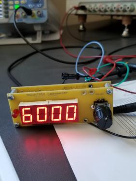
I have this tachometer tested and ready to go out to someone that can use it. All I ask for is the cost of shipping. I programmed in 10 slots or magnets for the testing. You can program it with your actual number. All the ranges tested worked from 2 - 97% duty cycle. I'm pretty sure it's edge triggered, interrupt driven.
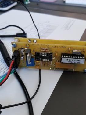
The board draws about 60mA of current at 9VDC. Depending on the sensor you choose, the current required will go up. Power it with a 9VDC wall wart, or any other 9VDC source. Just make sure it's an electrically clean power supply. If you have problems with erratic readings you can add a filter choke in between the power supply and the tachometer. Some installations have been electrically noisy and needed the filter choke to stabilize the readings. This particular board is one of the older versions. It had a smaller surface mount 5VDC regulator which got too hot for comfort so I replaced it with one that's in a larger package, TO-220. I epoxied it down to stabilize it to the board. I ran a burn in test on it and the TO-220 barely got warm. The newer boards switched to the TO-220 package.
The connector is a TE Connectivity AMPMODU MTE series 6 pin connector. I can include the mating connector with 12" leads if you'd like.
The frequencies listed below are the PWM frequencies from the signal generator. at 5VDC output.
5Hz = 30RPM
10Hz = 60RPM
20Hz = 120RPM
100Hz = 600RPM
200Hz = 1200RPM
500Hz = 3000RPM
1000Hz = 6000RPM
Ed
P.S. I have two more boards that need to be assembled and tested. Then I will also be offering these for the cost of shipping.


