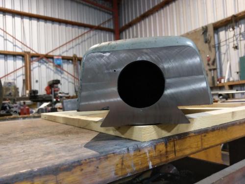
Frankenmill: Bridgeport J head onto Victoria U2
#21
Having the tractor out of the shed has enabled me to put a little energy into the frankenmill. I wheeled out the spare overarm, nice to have a potentially sacrificial unit if this all goes pear shaped.
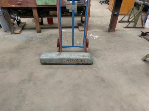
   
As suspected, the little badge on the front end of the ram hides a hole, presumably where the casting core would have been cleaned out from. Access to the hollow should prove handy.
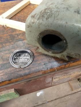
   
I was expecting to find a series of gussets inside the casting as in this image http://www.lathes.co.uk/victoria/img4.gif but the casting is a simple hollow section with no gussets at all.
The challenge is to reproduce the tilt section of the BP knuckle on the front end of the U2 overarm.
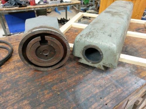
   
I mounted the overarm on the mill table and used a face mill in the main spindle to cut a plane on the front end. Lots of weight hanging off the front of the table.
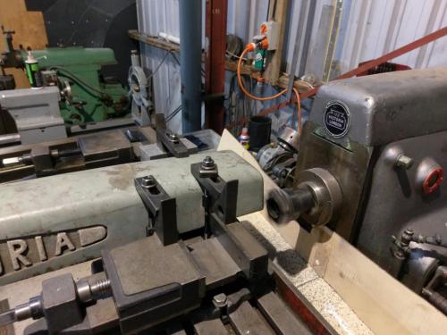


I need to find a couple of pieces of heavy plate to make the adaptor arrangement, tried two scrap metal merchants today but no luck, this project will be dependent on finding some suitable plate. I did find a suitable lump of scrap for another project though.

I'm currently waiting on a delivery from the US of the parts needed to complete the J-head rebuild, plus a MachTach the will go in as it goes together.
Lathe (n); a machine tool used in the production of milling machine components.

Milling Machine (n); a machine tool used in the production of lathe components.
Reply
Thanks given by:
#22
I had to make a pair of angle fixtures in order to be able to machine the sides of the overarm to accept a pair of cheek plates, these plates will be bolted to the sides of the overarm with another plate bolted down to the top of the cheek plates and the adaptor will be bolted to the front face of those three plates.
The two sides of the overarm casting are not planar surfaces but they are reasonably close to flat right at the front end where I need to attach stuff. The flat-ish surfaces are not quite at the same angle on the two sides
   
   
so I decided to split the difference and work to 80.5 degrees both sides.
I needed to make a pair of angled fixtures to clamp the overarm down onto. Found an offcut of the plate i used for the shaper table extension last year. Squared it up on the mill (this whole job is having to be done in stub-milling mode)
   
and then surfaced it in the shaper. Can't wait to get the frankenmill finished- the shaper is very slow with this sort of work
   

Split it on the bandsaw at something approaching the appropriate angle
   
I clamped the two halves together, drilled and reamed a couple of 12mm holes through them and dowelled them together so they could be milled as a matched pair.
Then I spent aaages setting up to mill the angle into them. Not having any guage blocks, I found a piece of scrap that was just over the required thickness and then used the surface grinder to get it down to the right thickness to set the sine bar up. As if the stub-milling business isn't awkward enough in itself, working at the back of the job all the time, the only sine bar I have is wider than the base of my vice so I had no end of stuffing about to get the sine bar in place to set the angle plate to the correct angle.
   
Clamped the pair of plates somewhere in behind all this so I couldn't see what I was doing and then milled them to the required angle plus a step to sit the side of the overarm dovetail against.


One day I'll get some good machinist squares but I reckon this was near enough for the purpose
   
drilled and counterbored to accept some half-inch socket-head capscrews;
   
Just to make this job drag out a bit, I couldn't get whitworth-threaded SHCS, all my T-nuts are 1/2" whitworth, had to use UNC capscrews and make some T-nuts to suit.
Finally got them bolted down to the mill table. When I say finally, I actually ended up having to move them forward so that the surface to be milled hung over the inside edge of the table, so I could use the outer t-slot to clamp it down, the overarm is too long to be able to clamp at the ends.
The end face of the fixtures was measured off the face of the column to get the step parrallel to the X-axis.
   

I milled one side of the overarm tonight, would you believe I forgot to take photos of the setup. I'll try and remember to take a photo when I do the other side.
   
Lathe (n); a machine tool used in the production of milling machine components.

Milling Machine (n); a machine tool used in the production of lathe components.
Reply
Thanks given by:
#23
This project continues to dash along at a positively stunning rate. I've been doing some work on getting the cheek plates attached to the overarm, along with some foundry upgrades so I can cast the front adaptor piece. We've been having some improved weather of late and today was forecast to be the warmest day we have had on months so I've been doing a lot of sanding, filling, sanding, sanding sanding and today I got the colour on the J-head casting and components. That thing was an absolute pig to prepare, was nice to finally get it shiny.


Lathe (n); a machine tool used in the production of milling machine components.

Milling Machine (n); a machine tool used in the production of lathe components.
Reply
Thanks given by:
#24
I don't think they put much effort into smoothing out those castings. They just put a crap load of filler on and sand it down.

Looks great, Pete!

Tom
[Image: TomsTechLogo-Profile.png]
Reply
Thanks given by:
#25
(10-19-2018, 09:27 AM)TomG Wrote: I don't think they put much effort into smoothing out those castings. They just put a crap load of filler on and sand it down.

Looks great, Pete!

Tom

You are so right Tom, I was a bit taken aback when I stripped the casting down to the metal, it appears to be a matter of cutting off the ingate and riser and then slathering it with bog. The surface of the bare casting was surprisingly rough. Also they are comprised pretty much entirely of nooks and crannies- a large proportion of the sanding was done with the side of my little finger.
Lathe (n); a machine tool used in the production of milling machine components.

Milling Machine (n); a machine tool used in the production of lathe components.
Reply
Thanks given by:
#26
No more progress on the overarm mount yet, my Bridgeport parts came so I've done some work on the J-head including installing a MachTach.

I decided to go with a hall sensor. I expected to have to recess the magnets into the bull gear face but a little test- I stuck a magnet to the gear, put the cover on and spun the gear- confirmed there was clearance between the top of the gear and the underside of the cover.


I confirmed a position above the housing where there was clearance from the timing belt. Drilled a hole in the gear cover and sighted through it to ensure the magnet passed under the hole, then used the dividing head to mark out the positions of the six magnets and placed them in position with a dab of epoxy to keep them there.
The red pencil line on the gear cover was traced on the side of the timing belt. Plenty of room at this end.


I milled a 8mm-wide groove in the top of the cover parallel with the line of the belt, finishing at the hall sensor hole.
   

Milled a 12mm-wide slot into the rim of the top housing to provide an exit point for the hall sensor cable


drilled a blind hole in the top face of the gear housing and tapped it 1/4-20 to take a cable clamp to keep the hall cable out of mischief


I did a little file work on the slot and hole for the hall sensor so I could lay the cable in the slot and bend the tabs on the sensor to get it down into the bottom of the hole without shorting on the metalwork anywhere. I used a lump of blu-tack to dam the bottom of the hole and then epoxied the sensor and cable in place. I had to use a couple of clothes pegs and matchsticks to hold everything in position whilst the epoxy cured overnight- couldn't avoid glueing a matchstick to the top of the cable so it ended up a bit messy but effective.


I was curious to see how the epoxy and blu-tack reacted with one another, I had to scrape the last bit of the blu-tack away from the sensor but it came away clean with not too much trouble. The hall sensor is visible in the hole from underneath:


I finished up assembly of the J-head. The hall cable comes out the side adjacent to where the control switch mounts. I plan to use a VFD and to mount a control panel with remote fwd/reverse/rpm pot as well as the machtach on the side of the motor cowl where the original switch sits. there's a fair bit of fibreglass repair work to do on the cowl and the top cover is missing.


I jury-rigged the machtach and gave the J-head a test run. Everything worked nicely including the power feed but the motor bearings are noisy so will be replaced before this goes into service. I was only game to run it in the slowest belt position with the head on the engine stand but it worked in high & low range and the machtach works a treat. The missing display element on the machtach in the photo is just the camera effect.


Strangely there is a gap between the top of the J-head main casting and the drive housing. I'm sure I haven't left anything out so I'm thinking perhaps this is because I didn't use any body filler on the drive housing- if it was a smidgeon fatter it would cover this gap. Unless there are better suggestions, I will seal it with a little silicon.

       
Lathe (n); a machine tool used in the production of milling machine components.

Milling Machine (n); a machine tool used in the production of lathe components.
Reply
Thanks given by:
#27
Lookin good so far!
Logan 200, Index 40H Mill, Boyer-Shultz 612 Surface Grinder, HF 4x6 Bandsaw, a shear with no name, ...
the nobucks boutique etsy shop  |  the nobucks boutique
Reply
Thanks given by:
#28
In between getting my property ready for the fire season and other chores, I managed to steal some more time on the frankenmill this week. I had something of a setback although it was not entirely unexpected. I discovered that the spare overarm that I have been doing the fitting work on will not fit the dovetails on the top of my mill. I knew that these machines were all individually finished by hand and components numbered and matched, but I guess I thought that it would be 'near enough for government work'. I tried to slide one of the arbor supports onto the dovetails of the spare overarm and it was just nowhere near fitting.

While this means that all the work I have been doing on the spare overarm will need to be repeated on the actual overarm from the machine, it is actually liberating in that I can now experiment on this one in the knowledge that it is sacrificial.

That being the case, I have had a fairly comprehensive re-think of how I am attacking this job. The angled fixtures that I made have been problematic in that I have not been able to hold the casting down to them as securely as I would like. I was mulling this over and thinking that maybe I could mount my two mill vices on angled fixtures and hold the overarm in both vices by the dovetail but it turns out my vices don't have sufficient jaw opening. BUT- I do have a shaper vice that has enough jaw opening to just about get the whole milling machine in.

While I was having a re-think about how to go about things, I decided it was time I had a decent size fly-cutter to mount in the NMTB40 horizontal spindle. Another spinoff project.
I found a rough chunk of unknownium plate that I had cut out with the oxy torch ages ago, turned it into a thick disc, bored a 1" hole through it, counterbored that to take a decent amount of weld, cut down a bent NMTB40 1" arbor (the one I was pathetically trying to straighten a year or so back) and stuck the two together. Once it had cooled down, I mounted it in the mill spindle and clamped a lathe tool to the table to face it again and then chamfer it. Drilled and reamed a 3/8 hole to take a round toolbit and another hole intersecting that to take a 5/16 grubscrew. I put a piece 3/8 round HSS in a mill vice plonked on the surface grinder chuck and ground a flat on one side for the grubscrew to engage on, then ground the end of it to look like my approximation of a cutting tool. Voila.
   
   
One more spinoff project complete. I have thoughts of also using this as a chuck mounting plate so I can use the horizontal arbor as a lathe and my rotary table as a ball turner. But I'm getting ahead of myself.

I set the shaper vice up on the mill (twice; the first time it was too far back to bring the work to the flycutter  Slaphead )  Tramming the vice with a jaw that looked like the surface of the moon was impossible, so I whipped the fixed jaw off and introduced it to the surface grinder. Not only was it rough, it was not anywhere near flat.
   

I'll need to make some new jaws for this vice some time. Later.
Using parallels on one side to get the angled side of the overarm vertical left only just enough jaw face to pick up the corner of the dovetail.


With the 48kg shaper vice and the 38kg overarm all offset to one side, I was a bit worried about tipping the mill over. That side of the base has the bit for the coolant pump sticking out, might be all that saved it. Think I'll have to support it somehow before hang it out the other side.
   

I milled the side of the casting all the way back to the 'Victoria' logo. I've got enough X travel to go a fair bit further and the setup in the vice is repeatable enough that I think I can move the casting along in the vice and mill the whole length of the overarm if need be. That is one of the things i decided to change- I don't think I have enough length back along the arm with the original setup.
   

I've had a couple of big forklift tines lying about for a while- I was going to use these on the rear of my tractor but I got a smaller pair that will be plenty big enough for that, so these are now a source of material.


That thing weighs 88kg. I sure as heck didn't get it in the bandsaw by hand.
Cutting the tine at it's thickest point, which will provide a face at the front end of the overarm, there is enough length to go all the way to the back end of the overarm. I'm undecided whether to use the whole length. Happy to hear opinions on that.
That was all I had time for before other commitments, tomorrow is Monday for me so hopefully more next week.
Lathe (n); a machine tool used in the production of milling machine components.

Milling Machine (n); a machine tool used in the production of lathe components.
Reply
Thanks given by:
#29
A little more progress, took the overarm out of the machine, stripped the bulk of the paint off with a wire cup wheel and milled the flats on the two sides. I've decided to take the cheek plates back to just before the name badge in the casting.


Cut a chunk out of each of the two 6" wide forklift tines for the cheek plates so that the thickest part of the tine will be at the front of the overarm. I mounted the vertical milling attachment- again- and set it up to bevel the bottom edge of the cheek plates.


This is to match the angle here


Those two jobs were far easier using the big vice than the previous attempts with the angle fixtures. Wish I could get the time back that I wasted there.

I mounted the rotary table and started the task of putting a radius on the back end of the cheek plates, hope to get that finished tomorrow so more photos to follow soon.
Lathe (n); a machine tool used in the production of milling machine components.

Milling Machine (n); a machine tool used in the production of lathe components.
Reply
Thanks given by:
#30
Good progress, Pete. Thumbsup

That beast of a fly cutter seems to be earning its keep.

Tom
[Image: TomsTechLogo-Profile.png]
Reply
Thanks given by:


Users browsing this thread: 9 Guest(s)