Lathe Tool Grinding Helper
#61
After my customary morning nap, I spent a few minutes aligning the vertical mill vise and edge finding the axes then started learning the DRO functions.  As previously noted, the manual for the thing is useless so I spent about ten minutes playing with the bolt circle function.

The commands on the display are not in any form of English that I'm familiar with but I muddled through and figured it out finally.  (E.g.  the word "end" is "ed" on the display and not because it lacks enough display characters, LOL.  I'm thinking that the software code was written by ed chang.

I started working on the Delrin block that forms the base for the tool holder (the camera tripod with the tiny vise).  Drilling the holes probably took half the time it normally would - no need to double-check every dimension before turning on the machine, LOL.  It only takes two or three minutes to calculate the X, Y dimensions from the bolt circle dimensions but again, there is the possibility of error.  (I sometimes print a full size copy of anything with unusual shapes or weird dimensions and rubber cement it on the part, to double check my dial crank turns.)

Anyway, here is the start of the Delrin block.  Tomorrow I'll do the boring and OD turning followed by some jeweler's rouge and a buffing wheel.

   
Reply
Thanks given by:
#62
My buddy kept laughing at my old DRO that had no functions, telling me how slick the bolt hole thing was. Never felt I needed one, could always get the hole locations off my drawings but made a puller the other day, no drawing. Used the bolt circle function to drill 3 of the holes to mate to the 5 bolt hub I was pulling. Have to admit, pretty slick. Think mine might have been made by ED too.
Free advice is worth exactly what you payed for it.
Greg
Reply
Thanks given by:
#63
Ha-ha-ha, my friend was over here yesterday pointing out all of those slick DRO features, in particular the bolt circle.

He said. "Think of how much time you could have saved over the years with that bolt circle feature."  I suppose that I didn't look too enthusiastic so he asked me when was the last time I had to manually calculate and drill a bolt circle.  I told him about sixteen years ago and he shut up.
It wasn't true, I actually have done bolt circles within the past year, I just couldn't take any more of his "I told you so" remarks. You Suck 

But as you say, Greg, it IS pretty cool !  And using the DRO gives me a feeling of confidence where I never felt confident using dials on a mill unless I checked the setting twice.  ESPECIALLY when milling pockets while referring to the little pieces of scratch paper with backlash figures jotted down and a sketch or two !

I'd read about the following feature but it didn't really "stick" until this morning:  the DRO system can be used as a measuring instrument (CMM ?).  With one of those pointy edge finders, it's a piece of cake to copy a hole pattern from an existing part.  I've used those dial calipers with conical ends that are designed for measuring hole patterns but they are limited to about five inches.  With the DRO, the only limit is the table travel  Thumbsup

I just finished printing about thirty pages from a CNC manual on line that has many of the same features as mine.  It is quite intelligible although some of the sentence structure is a little odd.  If anyone has any interest in the system that I bought, there are many of them for $200 + free shipping on eBay, like this one:

https://www.ebay.com/itm/2-Axis-DRO-Digi...SwtKVaaqrs

And this is the manual that is legible and has pretty much the same features as the above:

http://www.zsinstruments.com/downloads/D...l-V2.0.pdf

(usual disclaimer, no affiliation etc.)
Reply
Thanks given by: SteveG
#64
I started the lathe work on the "Delrin" base to which the camera tripod head will be mounted.  First step was to reverse the chuck jaws to grip the external edges of the square part.

A 3/8 hole had  been drilled through the center of the work at a previous step so centering was quick and easy.  With the chuck jaws loose and a center in the tailstock, the tailstock was moved forward until the center was snugly engaged in the 3/8 hole.  The jaws were then carefully tightened until the jaws just touched the work edges.

I used a one inch travel dial indicator secured to the lathe carriage to indicate the edges of the work, moving the indicator away from the work to clear it while rotating the chuck for measuring the opposite edge.  The part is rocked back and forth while the indicator is in contact with the approximate midpoint of the flat to find the lowest reading.  This is the reading that will be compared to the opposite side.  The chuck jaws are adjusted until both readings are the same (or within your desired tolerance) tightening a bit at a time until the part is chucked securely.

NOTE:  if the edges of the part were already at finish dimension, to avoid marring, I would have placed some scraps of metal between the jaws and the work to distribute the clamping pressure.

After centering, a two inch diameter x two inch deep hole is bored.  This is the back side of the part and will never be visible so I fed the boring tool by hand for speed and because I wasn't concerned about tool marks.


The next step is to knock off the corners of the part and turn it circular.  Had the part material been metallic, I would have sawed most of the material from the corners before turning.  But since the composition is "Delrin" plastic, I skipped that step.  Removing the chuck jaws and reversing them (again) the part was flipped and then chucked on the two inch bore which is b-a-r-e-l-y large enough to accommodate the jaws.

Because the cut was an interrupted one and because the chuck jaws extended only 3/4 of an inch, I used a tailstock center.  There's no way that the part can work it's way off the chuck with the center applying a little pressure.  Recall that there is a 3/8 hole drilled through the middle of the part so again I used it to center the part.  After centering, I countersunk it just enough to provide a seat for the tailstock center.

Here's the setup:


I was concerned about high spindle RPM causing melting at the point of the tool (I've been warned about this). So I used a moderate speed and fed the cutting tool by hand for roughing.  I did this because I was using very aggressive cuts, so aggressive in fact that I could hear the motor slow down, LOL, and I wanted to "feel" the cut, adjusting my feed until it felt comfortable.  

And because this surface is external and visible, I used a fine longitudinal power feed to make the final finish pass.


I don't like to spend more than an hour or two in the shop so I quit at this point.  Tomorrow I will reverse the part for some work on the other side.  This seems like a lot of switching back and forth and it is.  But it is also necessary because there must be a means of gripping the part for each operation and this sequence of operations provides for secure chucking at every step.
Reply
Thanks given by:
#65
One more milestone accomplished albeit a small one.  The base for the tripod head is done except for adding three teflon glides on the bottom.  The purpose of the ten holes can be seen in the photo below.  .458 cast lead bullets (NOT cartridges, just bullets for reloading .45-70 rifle cartridges) were placed in a pie pan over a stove burner to melt off the wax-base lubricant with which the bullets are coated.

The bullets were then epoxied into the holes in the base.  There is clearance in the holes on the back for installing the glides.


Here's the assembly with tripod head screwed to the base.  There are infinite degrees of freedom in this setup, the head can be adjusted to any elevation and rotation in any axis.  The height of the tool vise is controlled by sliding the vise mounting plate (with vee grooves) up and down in the vee ways of the head, then clamping in place.

The cast bullets add nearly a pound to the rear of the base to partly balance the weight of the vise and vise mounting plate.  In use, the tool to be sharpened is clamped in the small toolmaker's vise and adjusted to the correct angle and height.  The base of the tripod head is free to slide in any direction on the top of the aluminum jig plate.  The bullets provide enhanced stability.

The jig plate will be anodized, either dark blue or black.  Obviously, this will improve the appearance but is mostly for wear resistance, providing a hard, smooth surface for the teflon glides.


I haven't yet decided if I want to drizzle some black paint (or black epoxy) onto the top of the bullets for appearance - any opinions ?  The head needs to be removed so that I can buff out the base to remove some fine tooling marks
Reply
Thanks given by:
#66
Kind of like seeing the bullets, sort of a 'steam punk" look.
In the beginning design I thought the tool holder was fixed to the base.
Free advice is worth exactly what you payed for it.
Greg
Reply
Thanks given by:
#67
"Steam punk" ?  I LOVE IT, that's a great expression Greg !!
Reply
Thanks given by:
#68
I’ve been dozing for the past couple of weeks but I did several tasks today that I’ve put off for a while. After milling the large radius at the end of the grinding table , my last operation, I radiused the two front corners on the router table with a 1 inch corner rounding cutter.

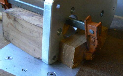
I don’t have a photo of the operation but it involved standing the grinding table on end and passing it along the fence of the router table. Even though this is normally done in several passes, routing aluminum in an unstable setup can be very dangerous !

The photo shows how I improved the stability and safety of the corner rounding process. The photo is a posed one since it was taken after the fact. A short length of 4 x 4 was clamped to the workpiece (with a scrap of wood on the top to prevent marring from the clamp).

The 4 x 4 provides excellent stability with a long surface to slide along the router fence. Additionally because the workpiece is backed up with the 4 x 4, there is no sudden break-out of the cutter, it just continues to cut but into the wood.
   

Next step was to do some corner rounding on the top of the table. I did this with a hand-held router and a ¼ inch corner-rounding cutter. I don’t know if I’m lazy, picky or what but I HATE to change router cutters; it only takes a minute but I just don’t like to do it.


My solution is to buy any router less than $25 that appears on craigslist or that I see at a garage sale. There are tons of these old Craftsman routers around and I have six of them plus a pair of Chinese trim routers, a sweet 1-1/2 horsepower DeWalt and a 3-1/2 horsepower variable speed Milwaukee with ½ inch collets that is the Big Dog of the bunch. (In the router table, it’s almost like running a shaper, LOL.)

Two are in router tables and the DeWalt is in a “radial router” that I devised. There used to be a jig to mount a router to a conventional radial arm saw but I haven’t seen them in years and they were sort of a clunky apparatus. Besides I need my radial arm saw so I made the radial router from scraps and it works well, especially for dado-ing large shelving and angular cuts that must be precise and repeatable.  In the interest of convenience and saving space, the router is mounted on the radial arm saw table.

Rear view mirror of my Harley is partly blocking the bottom of photo but a pin is visible (just above the mirror) which is a tight fit with a steel bushing epoxied into the table.  The router can be locked in position, centered on the pin and becomes a pin router.  I've turned four or five different diameter pins that fit the steel bushing and establish various offsets for the cutter.


There are adjustable stops on the router rails which set travel limits.  There are adjustable stops on the table, although they are not installed at the moment.  Obviously the entire assembly can be adjusted both vertically and angularly (is that a word ?).

All ten of the routers have different cutters more or less permanently installed, excepting the router tables and radial arm router. But I still whine about changing cutters because my shaky hands require most of my work to be done on the router table. Here’s a close-up photo that shows the results of me trying to rout by hand.  Note the occasional "divot".


The next chore was shearing the electrical panel that will be mounted between the pair of front legs of the grinding table. Once the panel is done, it and the table will be sent down to Santa Rosa, CA for anodizing. That’s the closest (450 mile round trip) plating facility for those of us who live “Behind The Redwood Curtain”.


Note that the bolster bar of the little shear has been removed (the spring loaded bar that clamps the workpiece as the shear blade is lowered).  This was to provide better visibility so that I can shear to any layout lines on the work.  Scrap pieces of metal or wood plus a couple of vise grips take the place of the bolster bar, as shown.

After shearing the front panel. The front two legs are to be slotted to accept the panel, which will slide into the slots. I expected the fit to be close to a press fit but if not, a few dabs of epoxy would secure the panel to the legs. With the legs installed on the grinding table and clamping the front panel to the legs, I marked the legs for the location and length of the slot.

Here's one of the legs secured in the milling vise, held by a collet block


If you look closely one of the two angle plates on either side of the collet block is visible.  These are for establishing a 7 degree angle for the panel slots.  The piece of masking tape on top of the leg is marked to indicate the end of the slot.

I spent a while filing and sanding away at three edges of the panel to obtain a good fit (have to tap all of the parts together) with the slots in the legs. Obviously this photo was taken before de-burring the plastic legs from the slotting operation.


Enough for the day.  I'll position and machine the mounting holes for the electrical components tomorrow.
Reply
Thanks given by:
#69
The radial router is really neat Randy.
Free advice is worth exactly what you payed for it.
Greg
Reply
Thanks given by:
#70
(02-16-2018, 08:49 PM)f350ca Wrote: The radial router is really neat Randy.

Thank you, sir.

I'd like an opinion from you guys (gals too):

What color should the base plate and the panel be anodized ?  I've been thinking a very dark blue or a black.  But I can also sort of visualize dark red or very dark green.  Slow as I am, the time for sending these things out is approaching 

The rest of the parts are mostly black and some bare chrome-plated metal - the grinding wheel guard will be a very dark grey (I happen to have a couple of sheets of dark grey PVC).

Any thoughts ?
Reply
Thanks given by:


Users browsing this thread: 6 Guest(s)