I’ve been dozing for the past couple of weeks but I did several tasks today that I’ve put off for a while. After milling the large radius at the end of the grinding table , my last operation, I radiused the two front corners on the router table with a 1 inch corner rounding cutter.
I don’t have a photo of the operation but it involved standing the grinding table on end and passing it along the fence of the router table. Even though this is normally done in several passes, routing aluminum in an unstable setup can be very dangerous !
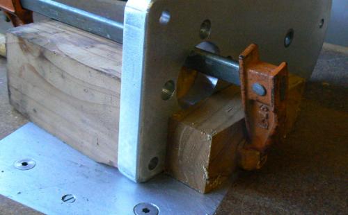
The photo shows how I improved the stability and safety of the corner rounding process. The photo is a posed one since it was taken after the fact. A short length of 4 x 4 was clamped to the workpiece (with a scrap of wood on the top to prevent marring from the clamp).
The 4 x 4 provides excellent stability with a long surface to slide along the router fence. Additionally because the workpiece is backed up with the 4 x 4, there is no sudden break-out of the cutter, it just continues to cut but into the wood.

Next step was to do some corner rounding on the top of the table. I did this with a hand-held router and a ¼ inch corner-rounding cutter. I don’t know if I’m lazy, picky or what but I HATE to change router cutters; it only takes a minute but I just don’t like to do it.

My solution is to buy any router less than $25 that appears on craigslist or that I see at a garage sale. There are tons of these old Craftsman routers around and I have six of them plus a pair of Chinese trim routers, a sweet 1-1/2 horsepower DeWalt and a 3-1/2 horsepower variable speed Milwaukee with ½ inch collets that is the Big Dog of the bunch. (In the router table, it’s almost like running a shaper, LOL.)
Two are in router tables and the DeWalt is in a “radial router” that I devised. There used to be a jig to mount a router to a conventional radial arm saw but I haven’t seen them in years and they were sort of a clunky apparatus. Besides I need my radial arm saw so I made the radial router from scraps and it works well, especially for dado-ing large shelving and angular cuts that must be precise and repeatable. In the interest of convenience and saving space, the router is mounted on the radial arm saw table.
Rear view mirror of my Harley is partly blocking the bottom of photo but a pin is visible (just above the mirror) which is a tight fit with a steel bushing epoxied into the table. The router can be locked in position, centered on the pin and becomes a pin router. I've turned four or five different diameter pins that fit the steel bushing and establish various offsets for the cutter.

There are adjustable stops on the router rails which set travel limits. There are adjustable stops on the table, although they are not installed at the moment. Obviously the entire assembly can be adjusted both vertically and angularly (is that a word ?).
All ten of the routers have different cutters more or less permanently installed, excepting the router tables and radial arm router. But I still whine about changing cutters because my shaky hands require most of my work to be done on the router table. Here’s a close-up photo that shows the results of me trying to rout by hand. Note the occasional "divot".

The next chore was shearing the electrical panel that will be mounted between the pair of front legs of the grinding table. Once the panel is done, it and the table will be sent down to Santa Rosa, CA for anodizing. That’s the closest (450 mile round trip) plating facility for those of us who live “Behind The Redwood Curtain”.

Note that the bolster bar of the little shear has been removed (the spring loaded bar that clamps the workpiece as the shear blade is lowered). This was to provide better visibility so that I can shear to any layout lines on the work. Scrap pieces of metal or wood plus a couple of vise grips take the place of the bolster bar, as shown.
After shearing the front panel. The front two legs are to be slotted to accept the panel, which will slide into the slots. I expected the fit to be close to a press fit but if not, a few dabs of epoxy would secure the panel to the legs. With the legs installed on the grinding table and clamping the front panel to the legs, I marked the legs for the location and length of the slot.
Here's one of the legs secured in the milling vise, held by a collet block

If you look closely one of the two angle plates on either side of the collet block is visible. These are for establishing a 7 degree angle for the panel slots. The piece of masking tape on top of the leg is marked to indicate the end of the slot.
I spent a while filing and sanding away at three edges of the panel to obtain a good fit (have to tap all of the parts together) with the slots in the legs. Obviously this photo was taken before de-burring the plastic legs from the slotting operation.

Enough for the day. I'll position and machine the mounting holes for the electrical components tomorrow.


