08-07-2017, 10:45 PM
This a project from a few years back. Since rotary broaching seems still to be of interest to home machinists like me, my simple design doesn’t take long to make and might be useful for satisfying one’s curiosity about how these things work and the useful operations that can be performed with them.
I’ve been looking at shop-made rotary broaching tools for a while, thinking that one could be handy when a small internal feature is occasionally required. Finally I decided to make one employing a personally devised configuration:
 broach3.jpg (Size: 19.78 KB / Downloads: 205)

Most shop-made rotary broaches that I’ve seen are relatively large with more capability (and complexity) than I need. I made the compact design shown above by using a single hardened ball, for both thrust and positioning and which runs in wheel bearing grease. The body of the tool holder and the shank are drill rod, hardened moderately. I would have used pre-hardened 4140 if I’d thought of it.
(Incidentally, the black finish on the various parts is a result of the heat treatment. Hacks like me heat treat with an oxy/acetylene torch and a can of used motor oil.)
The shank of the broaching tool was turned to ,500 diameter so that it would fit any chuck on any machine in the shop. Maybe one of these days I’ll try something really weird like trying to broach with the old Milwaukee ½ hand drill, ha-ha.
The ball sockets in the broach holder and the shank were machined with a ball end mill held in the lathe tailstock after first drilling a small pilot hole to help out the slow, hard-working center portion of the ball end mill. This operation needs to be performed at really slow spindle speeds to obtain a nice finish (no chattering).
The broaching cutter itself was also made from drill rod but was of course, hardened more than the other two parts. I made two broaches; from inattention I ruined the first while torch-hardening the finish-machined part. The second one was turned to the finish diameters but only rough milled to cutting shape, leaving about .010 for a finish pass.
After hardening and drawing back to straw color in a toaster oven, I used a solid carbide end mill to bring the broach cutting surfaces to the finish dimensions (I have no surface grinder).
I don’t have photos of any of the machining operations so I’ll have to describe the process of finishing the broach as well as I can ... but I know that this will be confusing.
There are many ways to make this part and some will doubtless be more effective/convenient than the one that I chose. You might want to skip through all of this and just read a two-sentence summary about seven paragraphs down !
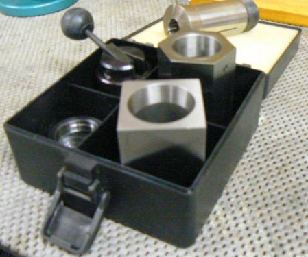
The rough-machined and hardened broach was first secured in a 5C square collet block like this one.

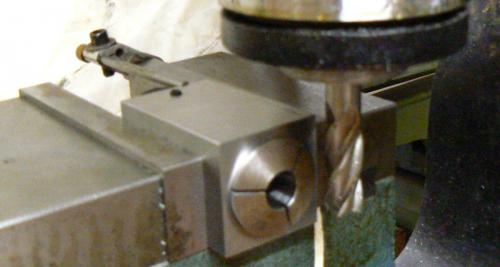
The collet block was clamped in the vise of my vertical mill. The vise was rotated about 4 degrees off normal angle to establish the relief angle of the broach. (This is a “posed” photo as previously mentioned because I have no photos of the original process, so there is no broach in the collet.)

My broach was octagonal so the procedure was slightly awkward. Continuing, a stop on the vise insured that the collet block is returned to the same location each time it is removed from the vise, turned 90 degrees, and replaced in the vise.
This occurs after each pass with the solid carbide end mill. After four sides have been cut to the required dimensions and angular relief on the sides, the collet block is removed from the vise.
Loosening the collet, the broach is carefully rotated 45 degrees and re-clamped insuring that the the length protruding from the collet is the same as the original length.
The remaining cutting surfaces of the octagonal broach are cut in the same fashion as the previous ones.
Before using the tool, I secured it a 1/2 inch R8 collet, placed in the vertical mill, powered up the milling machine and gently lowered the rotating broach against a hard Arkansas oil stone to polish the face a bit.
Or, in summary and described simply:
Secure the broach in a device that can index the desired spacing and that is set/mounted at the correct relief angle. Cut the broach to finish dimensions with a solid carbide end mill. (If you have a surface grinder then follow normal cutting tool profiling and sharpening procedure - if that means anything, LOL.)
In practice, an octagonal broach would be unusual. Hex shapes might often be required and these can easily be machined compared to the previous process. A hexagonal 5C hex collet block, like one pictured above next to the square block, could hold the broaching tool and all six sides machined without removing the broach from the collet block, although the collet block would have to be repositioned for each pass.
I didn’t make a radiused face like most shop-made broaches found on the internet. This was intentional and due to comments expressed by a guy (manufacturing engineer ? Foreman ? machinist ?) who worked for Volkswagen and was familiar with their rotary broaching operations.
He wrote that the “dished” cutting face diminished the time between sharpenings. He stated that,the sharper edges caused by “dishing” broke down more often and the breakage, seemingly not visible, could be seen under magnification as cratering and erosion of the cutting edge.
This can be important because, due to the back relief of the broach, the cutting tool is tapered ! Any sharpening of the face reduces the dimensions of the face. Further, removing material from the face of the broach changes the cutting angle, even if it is slight (see below).
I decided to give his opinion a try. I thought that I could always dish the face later if a flat face didn’t work properly. This is the first test drive.
 broach4.jpg (Size: 14.98 KB / Downloads: 208)
The hole is octagonal, .340 inches across the flats, .500 deep in CRS material. I made the pilot hole slightly oversize then countersunk generously (probably too generously) to provide a start for the broach.
In retrospect, rather than using a standard 82 degree countersink, I’d use a 60 degree center drill to make a smaller diameter countersink for introducing the broach into the hole.
Not only would the countersink be less obvious but instinct tells me that easing the broach into the pilot would be easier due to the steeper angle. I haven’t yet tried it but this is the original hole.
 broach5.jpg (Size: 23.05 KB / Downloads: 216)
For the first trial, the broach was run at 1000 RPM (just because that’s where the mill was set) applying a little pipe threading oil to the cutting edges. Total broaching time was on the order of two seconds ! I was highly impressed, everything I’d heard about these tools seemed to be true and it became apparent why they are used on screw machines !
Note that if the cutting angle is too great, the broach will not guide properly and it will wander, producing poor finishes and, more importantly, irregular dimensions.
If the cutting angle is not great enough, the sides of the broach will rub the hole, making a mess of the operation. The cutting angle is determined by the distance from the end of the broach to the center-line of the ball bearing and the eccentricity of the shank to the ball..
Knowing the dimensions of my holder, making various broaches the same length as the original will satisfy the angular requirement, I think. For those more patient than me, maybe a good method to optimize broach performance would be to make it slightly longer, broaching a trial hole and inspecting the appearance. Speed and feed could be varied if one had time and inclination.
The broach could be shortened slightly followed by another trial cut, repeating the process, inspecting each hole, until the hole has the desired appearance. (Even easier might be to make the broach intentionally shorter and then use spacers to gradually lengthen it to an optimum dimension.)
I didn’t do this, I established the dimensions of the parts so that the broach cutting angle was about 2 degrees. I read (somewhere) that it was a normal broaching angle.
Note that, whatever cutting angle is selected, the relief angle of the broach must be slightly greater. Further, the deeper the hole, the greater relief required.
It seems like this tool can be useful. I can reasonably quickly make custom broaches from 0.500 or 0.750 drill rod as the need arises. (I don’t envision producing an internal feature larger than .500.)
For my purposes, heat treatment is not critical so a torch and some used motor oil will suffice. I doubt that any broach that I make will be required to produce more than 10-20 parts.
Bearing that in mind, I had another thought: if the material to be broached was fairly soft, like most non-ferrous alloys, a short usage broach could be made from grade 8 fasteners. Grade 8 fasteners are pretty hard as manufactured, but can be worked with carbide tooling.
They are readily available from a local hardware store so I should try that some time. The cutting edges might have to be lapped a bit to sharpen them but the concept seems do-able for a run of 10-20 pieces.
Oh yeah, the rotary broach works in the lathe too:
 broach6.jpg (Size: 15.67 KB / Downloads: 215)
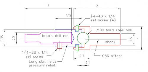
Here’s a dimensioned sketch:

The center-line of the shank is offset from the broach center-line by .050, as can be seen. This is what causes the broach to wobble and therefore cut. The offset distance and the length from the ball to the cutting edge of the broach is intended to produce a cutting angle of about 2 degrees.
The .050 offset was easily turned with the shank mounted in a four-jaw chuck. A travel indicator mounted on the carriage and touching the shank (before turning) made the setup dimension quick and precise.
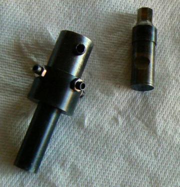
This is the disassembled broach holder and broach:
 broach2.jpg (Size: 16.77 KB / Downloads: 210)
Examining the drawing and the disassembled tool, one might question the function of the small #4-40 set screws - they serve no purpose when the broach is operating. They are positioned, secured with a tiny bit of "Loctite," in a large groove and they don’t touch any moving part.
The set screws prevent the shank, broach holder and ball from separating when the broach is not iin a tool-holder. I used four screws but two should be adequate for the purpose although three would look cool.
In one of the photos at the beginning of this post, it can be seen that there are four small socket head cap screws with lock-nuts performing this function. I didn’t happen to have any tiny set screws at the time and the cap screws were later replaced by set screws. Both work equally well but I liked the look of the tool with the set screws.
While looking for the original internet post describing my project, I found a rendition of my design by James Riser, who did a much better job than I did. I also looked at his website - he is a very ingenious, very talented,very capable guy !
His version of the broach, also including links to his finely-equipped home shop and some of his immaculate projects, can be found here:
http://jamesriser.com/Machinery/RotaryBroach/Build.html
Cheers,
randyc
I’ve been looking at shop-made rotary broaching tools for a while, thinking that one could be handy when a small internal feature is occasionally required. Finally I decided to make one employing a personally devised configuration:
 broach3.jpg (Size: 19.78 KB / Downloads: 205)
Most shop-made rotary broaches that I’ve seen are relatively large with more capability (and complexity) than I need. I made the compact design shown above by using a single hardened ball, for both thrust and positioning and which runs in wheel bearing grease. The body of the tool holder and the shank are drill rod, hardened moderately. I would have used pre-hardened 4140 if I’d thought of it.
(Incidentally, the black finish on the various parts is a result of the heat treatment. Hacks like me heat treat with an oxy/acetylene torch and a can of used motor oil.)
The shank of the broaching tool was turned to ,500 diameter so that it would fit any chuck on any machine in the shop. Maybe one of these days I’ll try something really weird like trying to broach with the old Milwaukee ½ hand drill, ha-ha.
The ball sockets in the broach holder and the shank were machined with a ball end mill held in the lathe tailstock after first drilling a small pilot hole to help out the slow, hard-working center portion of the ball end mill. This operation needs to be performed at really slow spindle speeds to obtain a nice finish (no chattering).
The broaching cutter itself was also made from drill rod but was of course, hardened more than the other two parts. I made two broaches; from inattention I ruined the first while torch-hardening the finish-machined part. The second one was turned to the finish diameters but only rough milled to cutting shape, leaving about .010 for a finish pass.
After hardening and drawing back to straw color in a toaster oven, I used a solid carbide end mill to bring the broach cutting surfaces to the finish dimensions (I have no surface grinder).
I don’t have photos of any of the machining operations so I’ll have to describe the process of finishing the broach as well as I can ... but I know that this will be confusing.
There are many ways to make this part and some will doubtless be more effective/convenient than the one that I chose. You might want to skip through all of this and just read a two-sentence summary about seven paragraphs down !
The rough-machined and hardened broach was first secured in a 5C square collet block like this one.
The collet block was clamped in the vise of my vertical mill. The vise was rotated about 4 degrees off normal angle to establish the relief angle of the broach. (This is a “posed” photo as previously mentioned because I have no photos of the original process, so there is no broach in the collet.)
My broach was octagonal so the procedure was slightly awkward. Continuing, a stop on the vise insured that the collet block is returned to the same location each time it is removed from the vise, turned 90 degrees, and replaced in the vise.
This occurs after each pass with the solid carbide end mill. After four sides have been cut to the required dimensions and angular relief on the sides, the collet block is removed from the vise.
Loosening the collet, the broach is carefully rotated 45 degrees and re-clamped insuring that the the length protruding from the collet is the same as the original length.
The remaining cutting surfaces of the octagonal broach are cut in the same fashion as the previous ones.
Before using the tool, I secured it a 1/2 inch R8 collet, placed in the vertical mill, powered up the milling machine and gently lowered the rotating broach against a hard Arkansas oil stone to polish the face a bit.
Or, in summary and described simply:
Secure the broach in a device that can index the desired spacing and that is set/mounted at the correct relief angle. Cut the broach to finish dimensions with a solid carbide end mill. (If you have a surface grinder then follow normal cutting tool profiling and sharpening procedure - if that means anything, LOL.)
In practice, an octagonal broach would be unusual. Hex shapes might often be required and these can easily be machined compared to the previous process. A hexagonal 5C hex collet block, like one pictured above next to the square block, could hold the broaching tool and all six sides machined without removing the broach from the collet block, although the collet block would have to be repositioned for each pass.
I didn’t make a radiused face like most shop-made broaches found on the internet. This was intentional and due to comments expressed by a guy (manufacturing engineer ? Foreman ? machinist ?) who worked for Volkswagen and was familiar with their rotary broaching operations.
He wrote that the “dished” cutting face diminished the time between sharpenings. He stated that,the sharper edges caused by “dishing” broke down more often and the breakage, seemingly not visible, could be seen under magnification as cratering and erosion of the cutting edge.
This can be important because, due to the back relief of the broach, the cutting tool is tapered ! Any sharpening of the face reduces the dimensions of the face. Further, removing material from the face of the broach changes the cutting angle, even if it is slight (see below).
I decided to give his opinion a try. I thought that I could always dish the face later if a flat face didn’t work properly. This is the first test drive.
 broach4.jpg (Size: 14.98 KB / Downloads: 208)
The hole is octagonal, .340 inches across the flats, .500 deep in CRS material. I made the pilot hole slightly oversize then countersunk generously (probably too generously) to provide a start for the broach.
In retrospect, rather than using a standard 82 degree countersink, I’d use a 60 degree center drill to make a smaller diameter countersink for introducing the broach into the hole.
Not only would the countersink be less obvious but instinct tells me that easing the broach into the pilot would be easier due to the steeper angle. I haven’t yet tried it but this is the original hole.
 broach5.jpg (Size: 23.05 KB / Downloads: 216)
For the first trial, the broach was run at 1000 RPM (just because that’s where the mill was set) applying a little pipe threading oil to the cutting edges. Total broaching time was on the order of two seconds ! I was highly impressed, everything I’d heard about these tools seemed to be true and it became apparent why they are used on screw machines !
Note that if the cutting angle is too great, the broach will not guide properly and it will wander, producing poor finishes and, more importantly, irregular dimensions.
If the cutting angle is not great enough, the sides of the broach will rub the hole, making a mess of the operation. The cutting angle is determined by the distance from the end of the broach to the center-line of the ball bearing and the eccentricity of the shank to the ball..
Knowing the dimensions of my holder, making various broaches the same length as the original will satisfy the angular requirement, I think. For those more patient than me, maybe a good method to optimize broach performance would be to make it slightly longer, broaching a trial hole and inspecting the appearance. Speed and feed could be varied if one had time and inclination.
The broach could be shortened slightly followed by another trial cut, repeating the process, inspecting each hole, until the hole has the desired appearance. (Even easier might be to make the broach intentionally shorter and then use spacers to gradually lengthen it to an optimum dimension.)
I didn’t do this, I established the dimensions of the parts so that the broach cutting angle was about 2 degrees. I read (somewhere) that it was a normal broaching angle.
Note that, whatever cutting angle is selected, the relief angle of the broach must be slightly greater. Further, the deeper the hole, the greater relief required.
It seems like this tool can be useful. I can reasonably quickly make custom broaches from 0.500 or 0.750 drill rod as the need arises. (I don’t envision producing an internal feature larger than .500.)
For my purposes, heat treatment is not critical so a torch and some used motor oil will suffice. I doubt that any broach that I make will be required to produce more than 10-20 parts.
Bearing that in mind, I had another thought: if the material to be broached was fairly soft, like most non-ferrous alloys, a short usage broach could be made from grade 8 fasteners. Grade 8 fasteners are pretty hard as manufactured, but can be worked with carbide tooling.
They are readily available from a local hardware store so I should try that some time. The cutting edges might have to be lapped a bit to sharpen them but the concept seems do-able for a run of 10-20 pieces.
Oh yeah, the rotary broach works in the lathe too:
 broach6.jpg (Size: 15.67 KB / Downloads: 215)
Here’s a dimensioned sketch:
The center-line of the shank is offset from the broach center-line by .050, as can be seen. This is what causes the broach to wobble and therefore cut. The offset distance and the length from the ball to the cutting edge of the broach is intended to produce a cutting angle of about 2 degrees.
The .050 offset was easily turned with the shank mounted in a four-jaw chuck. A travel indicator mounted on the carriage and touching the shank (before turning) made the setup dimension quick and precise.
This is the disassembled broach holder and broach:
 broach2.jpg (Size: 16.77 KB / Downloads: 210)
Examining the drawing and the disassembled tool, one might question the function of the small #4-40 set screws - they serve no purpose when the broach is operating. They are positioned, secured with a tiny bit of "Loctite," in a large groove and they don’t touch any moving part.
The set screws prevent the shank, broach holder and ball from separating when the broach is not iin a tool-holder. I used four screws but two should be adequate for the purpose although three would look cool.
In one of the photos at the beginning of this post, it can be seen that there are four small socket head cap screws with lock-nuts performing this function. I didn’t happen to have any tiny set screws at the time and the cap screws were later replaced by set screws. Both work equally well but I liked the look of the tool with the set screws.
While looking for the original internet post describing my project, I found a rendition of my design by James Riser, who did a much better job than I did. I also looked at his website - he is a very ingenious, very talented,very capable guy !
His version of the broach, also including links to his finely-equipped home shop and some of his immaculate projects, can be found here:
http://jamesriser.com/Machinery/RotaryBroach/Build.html
Cheers,
randyc


