Posts: 8,860
Threads: 319
Joined: Feb 2012
Location: Arizona/Minnesota
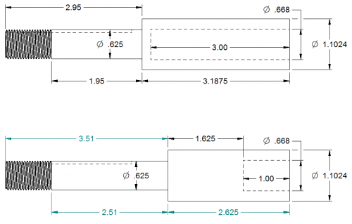
So I've got started on the power feed for my mill and am looking for opinions on making the lead screw adapter. Without modifying the lead screw, I'd need to bore a 3" deep, 17mm diameter blind hole in the adapter to fit over the existing lead screw. That sounds iffy for me so I'm thinking of cutting about 2" off of the lead screw that sticks out past the table and then I'd only need to bore a 1" deep blind hole. That hole needs to be a good fit on the lead screw shaft so it's as concentric as possible to the lead screw so the power feed doesn't bind. Either way, I'll be pinning the adapter to the lead screw with a spring pin. Any reason I shouldn't modify the lead screw and make it easy on myself? 
Ed
Posts: 3,003
Threads: 51
Joined: Apr 2012
Location: Ontario
You probably could cut the shaft but I'd hate not being able to put it back to stock if the mod didn't work out for some reason. Hey the mill could be a highly praised collectors item some day.
As for the adaptor it is pretty small to bore but probably do able. But what about using a 17 mm reamer, you like buying tools Ed.
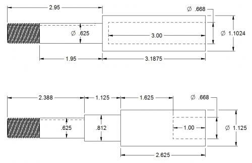
Or can you shorten the adaptor and only engage one inch of the shaft. i.e. go with the top drawing but shorten the 3.1875 section to 1.1875.
On the top design though, can you make it a little longer at the shoulder, there's not much material where the 0.668 bore meets the 0,625 dia. Probably ok but it wouldn't take much side load to shear out the 0.1873 section.
Free advice is worth exactly what you payed for it.
Greg
Posts: 2,685
Threads: 29
Joined: Feb 2012
Location: Nova Scotia, Canada
Ed, I see no problem in chopping off the leadscrew of the mill but what I don't understand is the other changes in the dimensions of the
adapter  .
Steve

Busy Bee 12-36 lathe, Busy Bee Mill drill, Busy Bee 4x6 bandsaw, Homemade 9x17 bandsaw, Ad infinitum.
Posts: 4,460
Threads: 184
Joined: Feb 2012
Location: Missouri, USA
Posts: 8,860
Threads: 319
Joined: Feb 2012
Location: Arizona/Minnesota
(01-11-2015, 01:41 PM)f350ca Wrote: You probably could cut the shaft but I'd hate not being able to put it back to stock if the mod didn't work out for some reason. Hey the mill could be a highly praised collectors item some day.
As for the adapter it is pretty small to bore but probably do able. But what about using a 17 mm reamer, you like buying tools Ed.
Or can you shorten the adapter and only engage one inch of the shaft. i.e. go with the top drawing but shorten the 3.1875 section to 1.1875.
On the top design though, can you make it a little longer at the shoulder, there's not much material where the 0.668 bore meets the 0,625 dia. Probably ok but it wouldn't take much side load to shear out the 0.1873 section.
Greg,
I could return it back to stock by making a new adapter so that's not an issue for me.
I don't mind buying tools when they will be useful. I can't justify buying a 17mm reamer to use once.
I could tweak the top drawing but another reason to modify the lead screw is then I can make the adapter work with the race that came with the power feed rather than having the needle bearing ride on the surface finish of the adapter which probably won't have the best of finishes for a needle bearing.
The only way to make the shoulder longer is to increase the length of the spacer which I could do since I haven't made the spacer yet. I have made the mounting bracket and don't want to remake it. Would .25" be good enough or should I go thicker?
I'm leaning towards cutting the lead screw. There are more benefits than drawbacks, I think.
Ed
Posts: 8,860
Threads: 319
Joined: Feb 2012
Location: Arizona/Minnesota
(01-11-2015, 01:43 PM)stevec Wrote: Ed, I see no problem in chopping off the leadscrew of the mill but what I don't understand is the other changes in the dimensions of the
adapter  . .
Steve

Steve,
Please ignore the dimensions. I was still playing around with them. The one below is what I should have posted.
Ed
Posts: 8,860
Threads: 319
Joined: Feb 2012
Location: Arizona/Minnesota
(01-11-2015, 02:38 PM)Highpower Wrote: (01-11-2015, 01:41 PM)f350ca Wrote: You probably could cut the shaft but I'd hate not being able to put it back to stock if the mod didn't work out for some reason. Hey the mill could be a highly praised collectors item some day.
Ed, I agree with Greg on this point. After going through what I had to do to adapt the power feed to the knee on my mill, I would say you are going to want as much of the original lead screw as possible for support and alignment of your adapter. I had to sleeve my adapter to get a good snug fit on the lead screw because the over sized bore allowed to much wiggle between the shafts and bound up the bevel gears in the power feed terribly. Even though the adapter screwed on tightly to the lead screw it flexed under a load without the sleeve. With only a one inch attachment/support I fear you would suffer the same problem with the "joint" flexing. (JMHO) I don't remember the exact length of the sleeve I made, but I believe it was at least 4 inches long, and I'm glad I have every bit of it now. 
Willie,
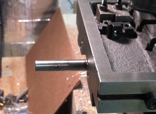
What's that thing sitting on the lathe ways in the second picture? 
Ed
Posts: 8,860
Threads: 319
Joined: Feb 2012
Location: Arizona/Minnesota
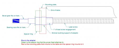
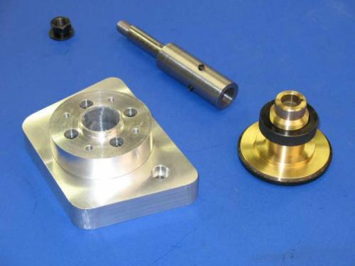
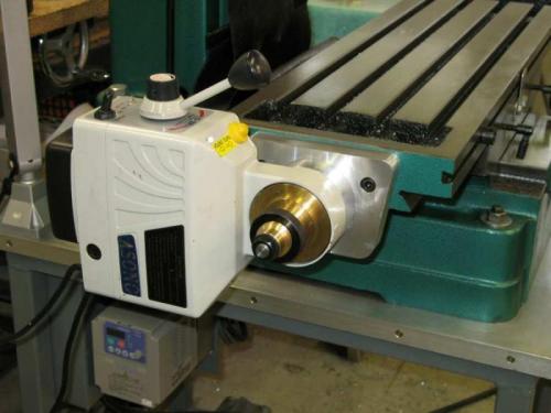
In an effort to clarify how my power feed is being attached to the mill, I made up the sketch below. I've also attached a couple of pictures showing the basic method I'm copying. That's how Henry installed his power feed on his RF-45 clone mill some time ago and it has worked out well for him.
In an effort to supply more support to the lead screw to prevent flexing at the junction of the adapter and the lead screw, which Willie experienced, I've drawn in a bronze bushing to support the end of the adapter where the lead screw engages.
Ed
Posts: 3,003
Threads: 51
Joined: Apr 2012
Location: Ontario
If your hel bent on cutting that pristine shaft, (just joking) how about a compromise. Cut one inch off and make the bore in your adaptor 2 inches deep. The extra support there should stop any flexing.
Try doing the bore first and see how it goes. Drill out to 5/8 and you won't have much to machine, go deep with the drill and ignore the point on the bottom of the hole.
Can you machine the adaptor with the lead screw attached? If so i'd be tempted to bore the hole 2 thou undersize heat it up and shrink fit it to the lead screw then machine the adaptor to run true to the thread. With a shrunk fit there would be no flex and all the elements would run true.
Free advice is worth exactly what you payed for it.
Greg
Posts: 8,860
Threads: 319
Joined: Feb 2012
Location: Arizona/Minnesota
How hot do I need to get it for a heat shrink fit?
Ed,
|


 .
.

![[Image: th_Knee_shaft.jpg]](http://img.photobucket.com/albums/v82/Highpwr/Knee%20Power%20Feed/th_Knee_shaft.jpg)
![[Image: th_Sleeve_OD.jpg]](http://img.photobucket.com/albums/v82/Highpwr/Knee%20Power%20Feed/th_Sleeve_OD.jpg)
![[Image: th_Slip_fit.jpg]](http://img.photobucket.com/albums/v82/Highpwr/Knee%20Power%20Feed/th_Slip_fit.jpg)
![[Image: th_Sleeve_bored.jpg]](http://img.photobucket.com/albums/v82/Highpwr/Knee%20Power%20Feed/th_Sleeve_bored.jpg)
![[Image: th_It_fits.jpg]](http://img.photobucket.com/albums/v82/Highpwr/Knee%20Power%20Feed/th_It_fits.jpg)
![[Image: th_Drive_unit_attached.jpg]](http://img.photobucket.com/albums/v82/Highpwr/Knee%20Power%20Feed/th_Drive_unit_attached.jpg)