Fixing a Leaky RF-45 Mill Head - Grizzly G0519
#51
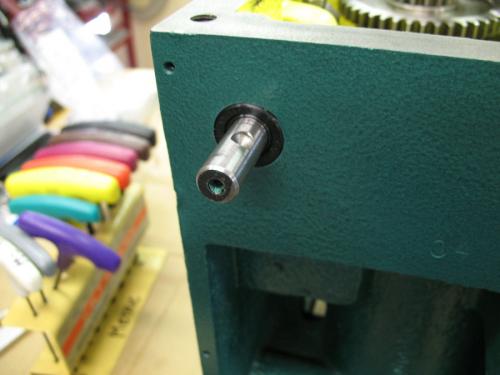
I'm now ready to start installing the gears and other hardware inside the head. The speed selector rods should be installed first because it's hard to install them after the gear shafts are installed. Remove the speed selector forks and then slide them in from the front. They are stopped by a circlip which I never removed. The seals go in after the rods are installed. Do not install the seals first because the seals hide the circlip and it's impossible to install the circlip if you install the seals first. Loosely install the selector arms. Later we will adjust them and tighten them up.
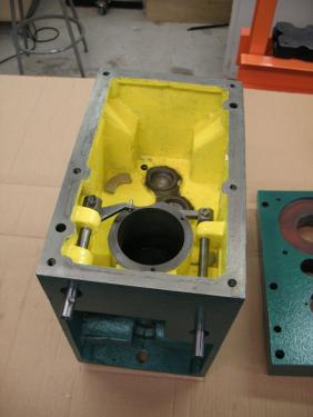
   
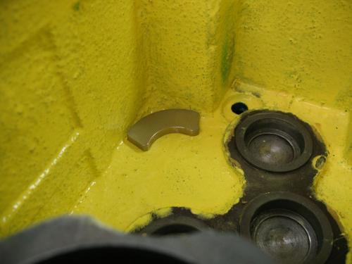
I had two powerful magnets. I put them in two of the corners of the bottom of the head. Some people prefer a magnetic dipstick or drain plug. This is what I already have. It should keep metal particles away form my bearings and gears.
   
Ed made a tool to drive the selector shaft seals. I happened to have this bearing/seal driver set which came from Harbor Freight. Either way, you'll need a tool to push the seals in without damaging them. The tool needs to be a little smaller than the diameter of the seal and have a clearance hole for the shaft.
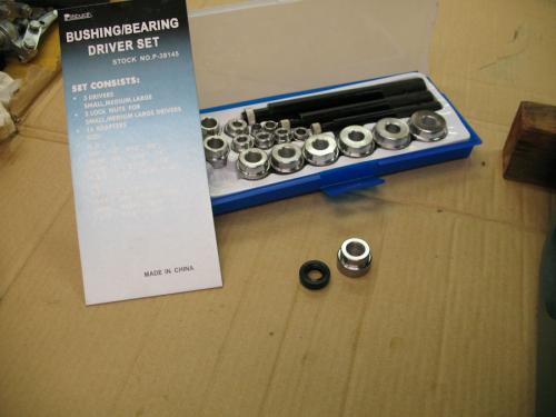
   
I used a driver with the correct diameter and then used another driver to extend beyond the length of the shaft. Tap the seals in with a rubber mallet. Many light taps are better than big blows for this job.
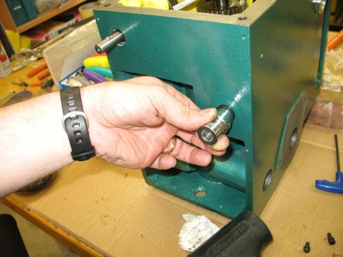
   
The seals should be flush with the surrounding metal. The front panel covers this area.
   
henryarnold, proud to be a member of MetalworkingFun Forum since Apr 2012.
Reply
Thanks given by:
#52
I'm now ready to install my gear shafts. I read a few posts and people have approached this different ways. Some have reinstalled the shafts in the gearbox lid which is the way it tends to come apart on some of these mills. The problem with this way of re-assembly is that it is very difficult to line up the gear selector arms and shoes. I decided to install my shafts into the bottom of the gearbox. I also decided to install the 5 smaller bearings that are on the ends of the shafts first.

It's probably confusing to know which gear shafts I'm referring to so here's a photo with the names I'll be using.
   
This is the 2nd Intermediate Shaft bearing installation both ends
   
   
This is the 1st Intermediate Shaft Bearing installation
   
I also installed a small bearing on the end of the Motor Shaft. No photo. You'll notice that I haven't been mentioning bearing sizes. That is because they vary from mill to mill. Mine are not the same as Ed's. You need to disassemble your mill to find out what you have.

My plan is to install the motor, 1st, and 2nd shafts into the gearbox and then press the lid onto the top bearings. The lid must have the spindle shaft because there is no support in the bottom half of the gearbox other than the seals. I found that the machining of both the lid and the bottom allows for a somewhat looser fit on the outside diameter of the bearings so that they slide into position with out much pressure.
henryarnold, proud to be a member of MetalworkingFun Forum since Apr 2012.
Reply
Thanks given by:
#53
Your doing a brilliant job of documenting this for other guys, great work.

Dave
Reply
Thanks given by:
#54
(05-10-2012, 11:33 PM)henryarnold Wrote: I had two powerful magnets. I put them in two of the corners of the bottom of the head. Some people prefer a magnetic dipstick or drain plug. This is what I already have. It should keep metal particles away form my bearings and gears.

Those old hard drive magnets are quite useful aren't they? Thumbsup

I have a couple in my lathe's headstock and apron as well for that very reason.

This is an outstanding thread on so many levels. Thanks for putting in so much work into sharing it with us Henry. Put it all in print and you would have an excellent service manual for that mill. Smiley-eatdrink004
Willie
Reply
Thanks given by:
#55
(05-11-2012, 01:10 AM)Dave J Wrote: Your doing a brilliant job of documenting this for other guys, great work.

Dave

Thanks. I probably would have taken the photos anyway because its hard to remember exactly how everything came apart. Ed and I are doing this job at the same time so our discoveries are helping each other and hopefully anyone else that needs to rebuild their mill head.
henryarnold, proud to be a member of MetalworkingFun Forum since Apr 2012.
Reply
Thanks given by:
#56
(05-11-2012, 06:17 AM)Highpower Wrote:
(05-10-2012, 11:33 PM)henryarnold Wrote: I had two powerful magnets. I put them in two of the corners of the bottom of the head. Some people prefer a magnetic dipstick or drain plug. This is what I already have. It should keep metal particles away form my bearings and gears.

Those old hard drive magnets are quite useful aren't they? Thumbsup

I have a couple in my lathe's headstock and apron as well for that very reason.

This is an outstanding thread on so many levels. Thanks for putting in so much work into sharing it with us Henry. Put it all in print and you would have an excellent service manual for that mill. Smiley-eatdrink004

Thanks.
Its funny that you know that those are hard drive magnets. We machinists/engineers think alike. If something is broken, take it apart, learn what's inside, and keep any useful parts. I know I'm in the right company when I hang out here. Big Grin

I plan to take the text and photos from this thread and create a PDF document. I belong to a Yahoo Group for the Dovetail Column mills and I want to post the photos and description there. Its also good to do this because sometimes threads get deleted so a document makes it easier bring it back.
henryarnold, proud to be a member of MetalworkingFun Forum since Apr 2012.
Reply
Thanks given by:
#57
This post will show the installation of the gear shafts and speed selector forks. As stated earlier, I decided to do my shaft installation in the bottom of the head. Some people have done the assembly on the top half. Either way results in some bearings being pressed into place by screwing the lid down.

The shafts drop in easily on my mill. The bottom bearing hole receives the shaft bearings with just a little pressure. Install the motor shaft first and then the 1st Intermediate shaft. They need to go in this order because the gears overlap the bearing on the previous shaft. While installing the 1st Intermediate shaft, line up the right selector fork and shoe. Look at the photos if you're not sure where the shoe rides.

I already installed my speed selector rods and loosely attached the forks that carry the selector shoes. My shoes had burrs around the holes so I used a countersink to remove the burr.
   
Although the gearbox will be bathed in oil, I thought it wouldn't hurt to put a little white grease on the shoe before installation.
   
Here's the right shoe installed.
   
Install the 2nd Intermediate Shaft while lining up the left hand selector fork and shoe.
   
This photo shows all three shafts that will be installed in the bottom half of the head. The selector forks need to be adjusted. I noted when I was disassembling the head that the forks were not screwed onto the shafts tight. There was a small amount of compliance determined by the set screw and retainer nut. During reassembly, I tightened the set screw all the way and then backed it off about a 1/4 turn and then tightened the nut. I'm not sure why the compliance is needed but it seems like the forks were designed to be slightly loose so I put them back they way I found them.

You may recall that I said earlier that the spindle shaft must be mounted in the top half of the head. There are no bearings for this shaft in the bottom half. I'll show the installation of the spindle shaft in a later post. In this photo you'll notice that the top bearing on the 2nd Intermediate shaft is installed. I had to remove this bearing and install it in the top half because it conflicted with a large gear on the spindle shaft.
   
henryarnold, proud to be a member of MetalworkingFun Forum since Apr 2012.
Reply
Thanks given by:
#58
(05-11-2012, 10:56 AM)henryarnold Wrote: We machinists/engineers think alike.

Unfortunately I am neither one. Blush

Just an old mechanic that was born with the DIY gene and likes to be as self-sufficient as possible. I do metalworking for the fun of it for the most part. (Hence my presence HERE.) I would starve to death if I had to try to make a living at it. Happyno

And my wife is the director of a huge I.T. department, so I have access to a lot of dead hard drives. Rotfl

What you are doing for the Yahoo group is very generous of you, and I'm sure they will appreciate your input as much as we do. We would like all our members to to post about there projects here - no matter how big or small. Somebody will benefit one way or another from the shared information. We can never learn it all. Smiley-eatdrink004
Willie
Reply
Thanks given by:
#59
In this post I'll show installation of the quill seal plate. Earlier I showed installation of the seals in this plate.
Originally the plate had just a gasket but since I am suspicious that a leak past this plate may have occurred, I use Permatex #2 on both the mounting surface and the plate. During installation the gasket squeezed out of place which is not good. I may have assembled it too soon. I'm not recommending this but I decided to leave the gasket out and to just use the Permatex. My mounting surface has a very thin edge near the 2nd Intermediate Shaft and I feel that the gasket could not be relied on to stay on that thin surface.
   
Throughout the reassembly I have replaced questionable hardware. These are new quality screws that I'm using to install the seal plate.
   
I decided to grease the seals concentrating on getting some grease between the two seals. My reasoning is that if the first seal does its job, no oil will reach the second seal and it will be running dry. I may be totally wrong on this.
   
Install the 3 circlips in the lid. There is one large one for the motor shaft bearing and two smaller ones for the intermediate shafts. I did not remove the circlip that was in the spindle shaft bore. You can see in the photo that its in place. The spindle shaft bor also has a spacer which I did not remove.
   
henryarnold, proud to be a member of MetalworkingFun Forum since Apr 2012.
Reply
Thanks given by:
#60
In this post I'll install the the Spindle Shaft in the top part of the head.

I already pressed one of the two bearings for the Spindle shaft onto the shaft. I could have used the press to push it into place but found that it went into place with light tapping of a rubber mallet. It rests against the circlip inside the bore. The second bearing is installed from the top.
   
Here's a photo from the top before installing the second bearing.
   
I had to modify the tool I made earlier to clear the top of the spindle shaft. The bearing rests below the top of the mill head and shaft. The bore in the tool provides the needed clearance.
   
Using the tool I pressed in the top bearing. This could have been done with the mallet but its easier to keep things straight using the press.
   
After I got the Spindle Shaft installed I realized I had a problem. This photo shows that the location for the top bearing of the 2nd Intermediate shaft conflicts with the gear on the spindle shaft. I took the spindle shaft out, moved the 2nd Intermediate shaft top bearing to the the lid and reinstalled the Spindle shaft.
   
   
Insert the circlip on the top of the Spindle Shaft.
   
All of the gear shafts are now installed.
henryarnold, proud to be a member of MetalworkingFun Forum since Apr 2012.
Reply
Thanks given by:


Users browsing this thread: 3 Guest(s)