Lathe Cross Slide Problem
#41
Normally the designer/draughtsperson would talk to the machinist (if they have some sense they will) and between them they will sort out what is what. The machinist nearly always has more experience in making a part than the designer/draughtsperson so it best to work together.
However this is not always possible especially when it is not known where the parts will be made, so it is important to convey in the drawing what is required.

Smiley-eatdrink004
DaveH
Reply
Thanks given by:
#42
(04-25-2014, 08:05 AM)stevec Wrote:
(04-25-2014, 05:54 AM)EdK Wrote: Steve,

I went back and reread your post and I guess I should have mentioned that there isn't enough meat on the gear to guide a drill bit. Only .080" thick which isn't enough for me to rely on for guiding a drill bit. That's why I am going to rotate it 90 degrees on the lead screw and drill a new hole.

Ed

Ed, maybe I should have said position the drill instead of "guide" it so as to start it in the same spot as the hole on the original.
However, you did mention that the gear was a loose fit originally so if you're going for a loose fit on the new leadscrew just disregard my ramblings. Cool

Steve,

Not a loose fit but a sliding fit, but maybe you're referring to a press fit versus a sliding fit. Chin

I'd rather read ramblings versus nothings.

Ed
Reply
Thanks given by:
#43
Let's try this again.

Ed


.pdf   leadscrew_04.pdf (Size: 33.29 KB / Downloads: 4)
Reply
Thanks given by:
#44
Ed, So far so good Thumbsup
The right hand side of the drawing perfect.
Just have to sort the left hand side a little.
If I add up all the dimensions 5.555+1.94+.5+8.59+.3 = 16.885. The overall length is given as 16.894. I know it is only .009" difference but "correctly" they should be the same.
Now you are "saying" you want the overall length to be 16.894 +/- .005 because it is a dimension with 3 decimal places. If it is critical that the overall length needs to be that accurate, then it does.Smile
Nevertheless the dimensions need to add up correctly, and what I would do is leave the 'clearance area for threading' with no linear dimension. The machinist will sort that out.
Or add the 8.59 dimension to the .50 dimension to give 9.09 and dimension it from the step to it's end point. Again leaving the 'clearance area for threading' actual length up to the machinist. You are not giving the machinist carte blanche it will still come out .50 +/- .02. because it is tied to the other dimensions and the overall length. Smile

Smiley-eatdrink004
DaveH
Reply
Thanks given by:
#45
One more.

Ed


.pdf   leadscrew_05.pdf (Size: 33.23 KB / Downloads: 9)
Reply
Thanks given by:
#46
Perfect Thumbsup Smiley-dancenana Worthy
Not as it will make any difference to Ken, he could do it with two and half dimensions and it would work and look good.
Ken is what I think is a proper machinist Smile
Smiley-eatdrink004
DaveH

PS I'm surprised Steve hasn't got something to say Rotfl
Reply
Thanks given by: EdK , stevec , PixMan
#47
I got the underside of the cross slide milled flat so now I need to find that elusive center height. Any good tips on the best way to measure that? 17428

Ed


With the existing nut sitting about where it was prior to milling the flat.

       
Reply
Thanks given by:
#48
Ken,

OK, I did my best to get a proper center height for the lead screw. I figure I can either shim it or skim it if it's off.

I did not draw the threads for the mounting screws. I'll use a transfer punch to locate them and drill and tap them myself. I think it'll be more accurate that way.

The location and size of the slit is based off of the existing nut which may not be correctly designed so go ahead and use your best judgement in machining this feature. I also didn't draw the threads for the set screw for adjusting the slit to remove backlash so you can use your best judgement again.

Let me know if I've missed something on the drawing.

Thanks Ken!

Ed


.pdf   nut_01.pdf (Size: 9.32 KB / Downloads: 7)
Reply
Thanks given by:
#49
Thanks Ed. I'll get one it as soon as I get done with painting my living room/dining room (big L-shaped room.) Should be a quick job to knock out.

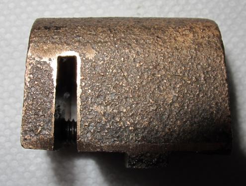
With a 10 TPI thread, you have barely 2-1/2 threads in that "adjustment" section. Most nuts like that I'd seen split in the middle so the halves wear evenly. I would also split it through the entire thread. Where is the adjuster on the original and how would you feel about having a cone point set screw coming through the cross slide casting instead of the hard-to-reach position of the original?

Also, how about radii on the upper corners as the original has? I've got corner rounding cutters, so it's easy.
Reply
Thanks given by:
#50
(04-27-2014, 07:31 PM)PixMan Wrote: Thanks Ed. I'll get one it as soon as I get done with painting my living room/dining room (big L-shaped room.) Should be a quick job to knock out.

With a 10 TPI thread, you have barely 2-1/2 threads in that "adjustment" section. Most nuts like that I'd seen split in the middle so the halves wear evenly. I would also split it through the entire thread. Where is the adjuster on the original and how would you feel about having a cone point set screw coming through the cross slide casting instead of the hard-to-reach position of the original?

Also, how about radii on the upper corners as the original has? I've got corner rounding cutters, so it's easy.

Ken,

Slitting in the middle is no problem. I don't think the way the current nut is slit is a very good design because the slit only goes half way into the thread.

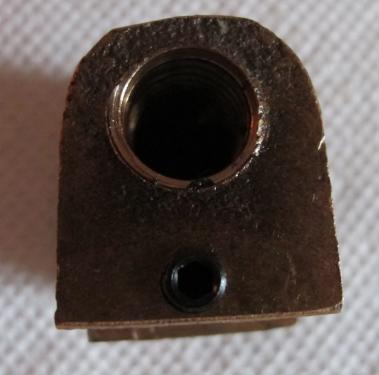
The adjuster is on the end of the nut facing the rear of the lathe. It's kind of hard to get to but not impossible. I don't have a problem with putting a set screw through the cross slide as long as it doesn't land in the spot where I took out that knurled bushing. I'm not visualizing how it would work though. Can you post a quick sketch as to how it would adjust the slit?

Radii on the upper corners would be nice.

By the way, while I was laying in bed last night trying to get to sleep, I realized I measured the center height improperly so a new drawing will be coming.

Ed

Sorry about the crummy pictures but I was in a hurry.
       
Reply
Thanks given by:


Users browsing this thread: 2 Guest(s)