Posts: 535
Threads: 39
Joined: Jan 2013
Location: Kelowna, BC, Canada
The following 2 users Like Hawkeye's post:
stevec (12-31-2013), EdK (12-31-2013)
12-31-2013, 12:46 AM
(This post was last modified: 12-31-2013, 12:49 AM by Hawkeye.)
In the 1950s and '60s, the Storebro Bruk 185-GK lathe came with a QCTP that was quite heavy and well made.
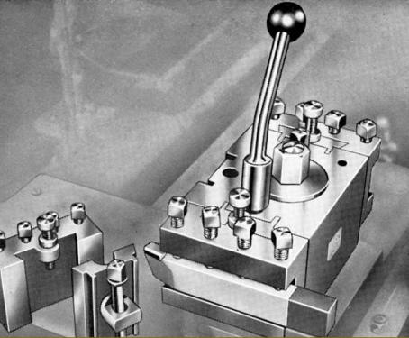
You'll notice that the centre section is large, with no features very close to the mounting bolt. I take this to indicate that the topslide on this lathe was made the same way as the earlier model like the one I just set up in my shop. There is a large post cast into the topslide, which is split into four segments. This post is a slip fit into a socket inside the toolpost. The bolt is tapered and expands like an inside collet when the nut is tightened.
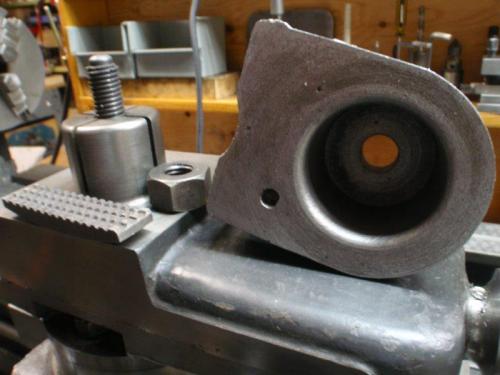
In order to make a QCTP that can fit on this lathe, it is necessary to work around this large post. In the Bergman toolpost supplied with the 185-GK, they used a rotating cam to pull in a dovetail section, which in turn pulled in the toolholder. Too many loose parts for my tastes. Some have made units with the clamping device in one corner, which serves to tighten two dovetail slots. I like this better, since the tightening force acts in the same direction that the work forces will try to push the toolholder.
On with the build. First, you take a piece of metal a bit bigger than you need.
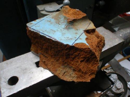
Then you remove everything that doesn't look like the part you want. Unfortunately, the scarf joint on my bandsaw blade let go during the fourth cut. I had to finish with the portable.
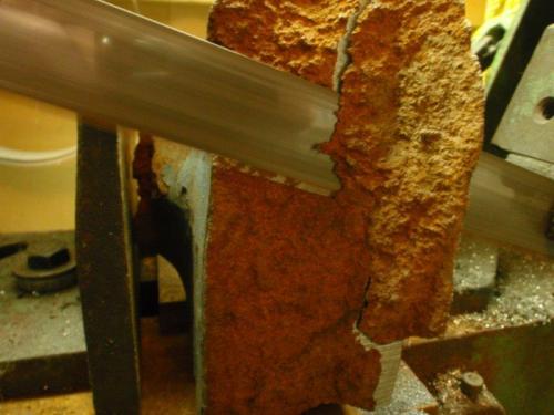
I used the lathe to face the larger surfaces, then went to the horizontal mill to true up the rest. Even with the mill running at the correct cutting speed, cast iron can burn. Note the spark trails.
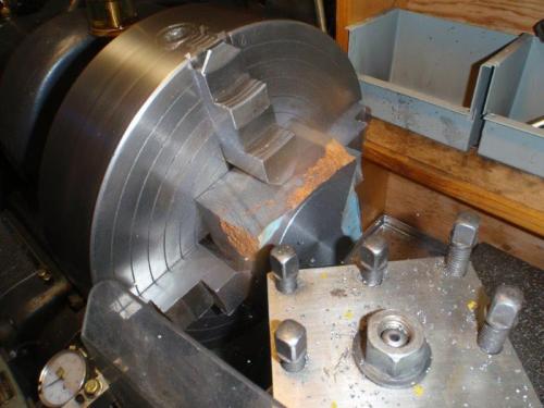
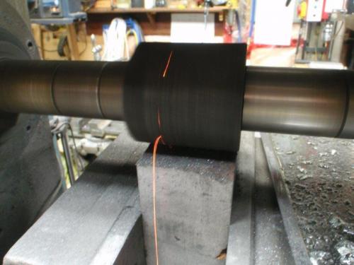
After the light show, I went back to the lathe and faced the remaining surfaces. Then it was time to create the socket to fit the topslide post. It took a awhile, especially as I was getting close to the ideal size. Nailed it.
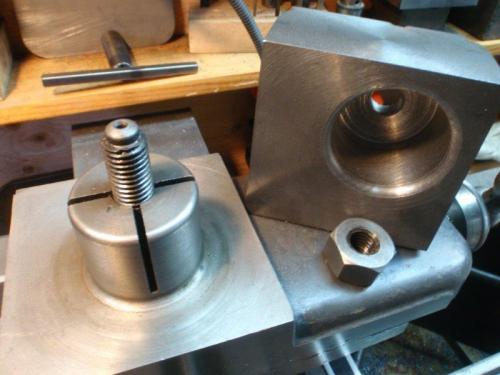
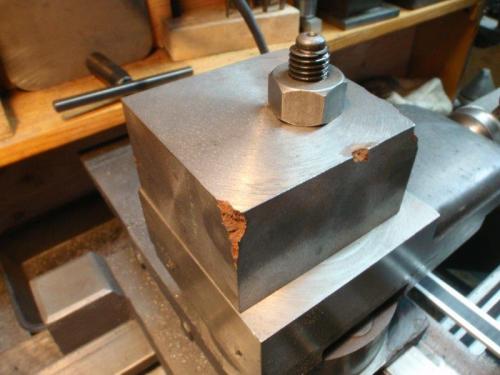
Tomorrow, dovetails. Once the toolpost is done, I'll need a long bar of steel to cut the individual toolholders out of. There are at least 12 different sizes of cutters I'll need to mount. For some sizes, I'll want several copies. I should plan on 20 holders. 
Mike
If you can't get one, make one.
Hawkeye, proud to be a member of MetalworkingFun Forum since Jan 2013.
Posts: 2,344
Threads: 53
Joined: Feb 2012
Location: Spencer MA USA
12-31-2013, 08:11 AM
(This post was last modified: 12-31-2013, 08:11 AM by PixMan.)
Quite an involved project.
I suppose if you had the stock lying around and have plenty of time to kill it's a fun thing. What kind of cast iron is that? It would appear to be a simple, soft gray cast iron rather than an 80Ksi ductile. Looking at the piece it appears to be a tiny chunk of a huge machine or heavy equipment.
Just so I'm clear, are you saying you are going with a more conventional type of QCTP that would accept simple one-piece tool holder block? In the top photos I see a two piece dovetail configuration that seems a lot of work. and plenty of opportunity for loss of rigidity. Even the idea of the indexing with that tapered screw/post style seems suspect, and no other lathes that I know of use it. It's mass does seem good though, no denying that.
I wish you the best and look forward to seeing your improved design for the tool block to post connection.
Posts: 3,003
Threads: 51
Joined: Apr 2012
Location: Ontario
Thats a neat design Mike. Does the stud/shaft have an eccentric that pulls the dovetail in to lock the tool holder?
Free advice is worth exactly what you payed for it.
Greg
Posts: 535
Threads: 39
Joined: Jan 2013
Location: Kelowna, BC, Canada
The following 3 users Like Hawkeye's post:
Mayhem (12-31-2013), EdK (01-01-2014), racer-john (01-03-2014)
As I said, the 1950s design had to many loose parts for my tastes. It actually had three toolholders - two ends and one side. Yes, the loose dovetail is pulled in to tighten the toolholder. In use, the Swedish toolpost proves to be extremely solid. It takes less pressure on the nut to lock it up - rather like the drawbar torque on an R8 accessory.
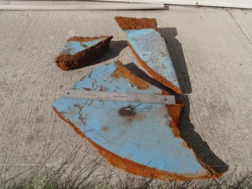
The cast iron was from some large broken pieces that I found at the local scrap yard. Proved to be really good material. As a bonus, the owner let me have them for free. I had just finished wiring his new shop at home and he was pleased to say the least.
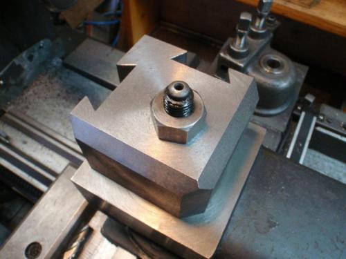
My toolholders will have a male dovetail that slides into one of two dovetail slots, as you can see here. (Told you I'd get them cut today.  ) The corner farthest from the camera will contain the clamping mechanism. A dovetailed insert will pull in between the two slots to clamp either or both toolholders.
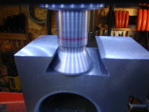
Back to the build. Here's the last pass on the second slot. I made the carbide dovetail cutter when I did the CNC conversion on my X2 mill.
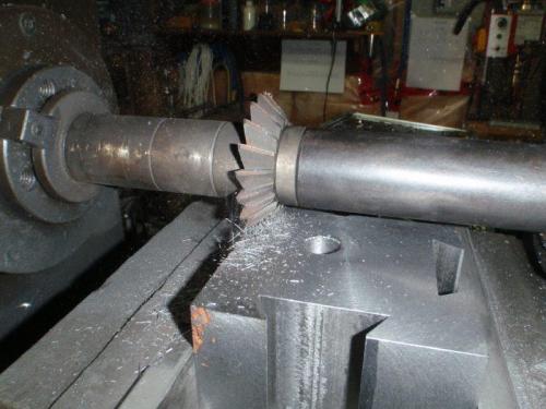
In order to make the cast iron block as large as possible, I left a few rough areas on some of the top corners. A 60* cutter in the horizontal mill finished off the back corners nicely. BTW, I found out what caused those sparks. On a horizontal mill, unlike a vertical, it's pretty easy to put the cutter on backwards. 
Mike
If you can't get one, make one.
Hawkeye, proud to be a member of MetalworkingFun Forum since Jan 2013.
Posts: 313
Threads: 34
Joined: Nov 2013
Location: Kamloops, BC, Canada
01-01-2014, 05:42 AM
(This post was last modified: 01-01-2014, 05:42 AM by Shawn.)
I bet if the fellow who gave you that cast iron knew what was inside it he would have kept it for himself.
Nice work Mike, I was wondering what else you might find in those broken old chunks of iron.
Shawn
Shawn, proud to be a member of MetalworkingFun Forum since Nov 2013.
Posts: 2,685
Threads: 29
Joined: Feb 2012
Location: Nova Scotia, Canada
(12-31-2013, 09:22 PM)Hawkeye Wrote: I found out what caused those sparks. On a horizontal mill, unlike a vertical, it's pretty easy to put the cutter on backwards. 
It's a relief to many of us that an accomplished machinist like you can make a boo-boo from time to time. 
Happy New Year and keep up the GOOD work. 
Busy Bee 12-36 lathe, Busy Bee Mill drill, Busy Bee 4x6 bandsaw, Homemade 9x17 bandsaw, Ad infinitum.
Posts: 139
Threads: 14
Joined: Apr 2012
Location: Nelson, BC, Canada
Mike
Was going to stop in and say hi Saturday, as I ended up doing an emergency drive the step daughter and grandchild back to K-Town, but ended up with the bug that was the reason for driving them back instead of her driving herself.
Oh well next time I'm up I'll make sure to come over so we can swap lies. LOL
Awesome looking work on your latest projects.
Walter
starlight_tools, proud to be a member of Metalworking Forum since Apr 2012.
Posts: 535
Threads: 39
Joined: Jan 2013
Location: Kelowna, BC, Canada
Never mind the projects, Walter. Lots of new tools!
Hope all are on the mend.
Mike
If you can't get one, make one.
Hawkeye, proud to be a member of MetalworkingFun Forum since Jan 2013.
Posts: 535
Threads: 39
Joined: Jan 2013
Location: Kelowna, BC, Canada
The following 1 user Likes Hawkeye's post:
stevec (01-03-2014)
No shop work yesterday. I needed to design a bunch of toolholders so that I knew the best way to make up the clamping mechanism.
Today, I got to work on the toolpost. First job was to cut the slot where the clamp would go. I love the power of a big horizontal. That's a 3/4" x 6" cutter. I chickened out and cut it in two 1/2" deep steps, instead of the whole depth at once. I'm sure it could have done it, but a slip at this stage would kill the whole project.
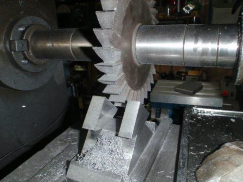
The finished slot.
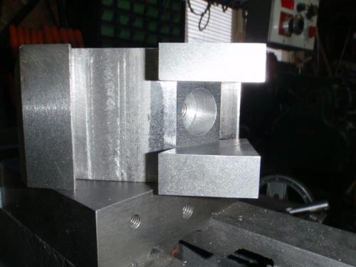
Now the clamp itself. I started with a slice of 2" square HRS, squared up on the U2. Mounted in the four-jaw To turn the underside.
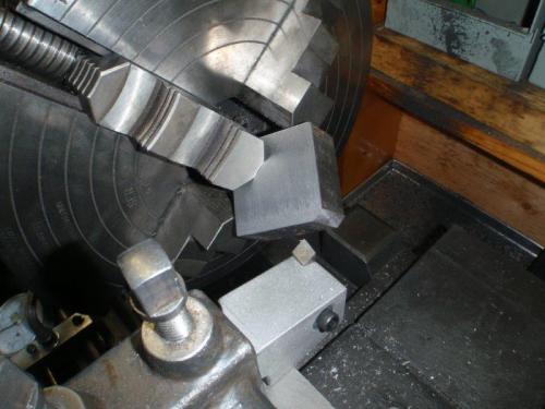
Lathe work done. Shaving the sides down for a good fit in the slot.
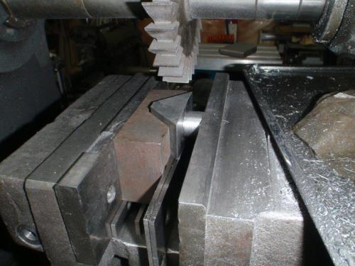
The clamp set in place and the dovetails being cut.
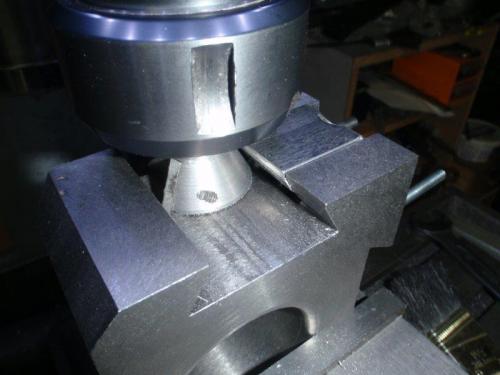
The toolpost is finished and ready for the toolholders.
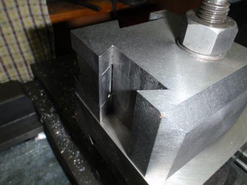
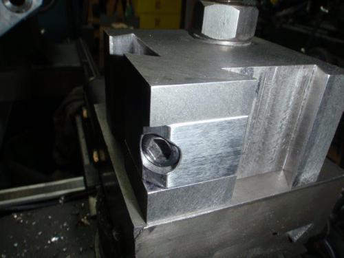
For now, the clamp is tightened by a bolt at the tip. It's done in such a way that I can later modify it to be operated by a camlock or a bolt-operated wedge. The current bolt would then become a means of adjusting the tension.
Mike
If you can't get one, make one.
Hawkeye, proud to be a member of MetalworkingFun Forum since Jan 2013.
Posts: 2,344
Threads: 53
Joined: Feb 2012
Location: Spencer MA USA
That's so nice. If later you can find a way to actuate the locking block via a cam and have a lever on top that would really make it a "Quick Change" type. I feel a true QCTP, just like a quick change gear box for threading, should be operable without a wrench.
One thing I'm curious about is the 3rd photo, where you show the part in a 4-jaw chuck. How is that part staying in place with only two jaws really clamping it? Looks scary to me.
|


 ) The corner farthest from the camera will contain the clamping mechanism. A dovetailed insert will pull in between the two slots to clamp either or both toolholders.
