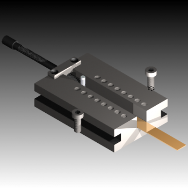
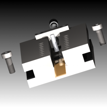
OK... A couple of initial teasers - I'll upload the Proper Drawings once I've got them into "paper space" and annotated all the dimensions (particularly those that would change for other chucks and scrolls) - a brief rundown...
The main slot needs to be precisely fitted for the jaws, and the jaw blanks need their key slots machined nice and parallel with the "non-tooth" face before cutting the scroll teeth;
the Very Observant will notice that the slot is offset from the locating sockets in the base - this is a *critical* dimension, equal (math don't fail me...) to the scroll pitch divided by 2xPi, so in the case of my 3tpi jaws, 0.053052" - drop the last digit and it should still work acceptably...

there are two sockets, precisely 0.500" diameter in the underside, for a spigot on the end of a MT2 short arbor - these are fairly critical, and need to be on centres equal to the difference between the scroll inside and outside radii - this very much simplifies using the thing!
In addition to the side clamping slots, there are countersunk holes for screws to go into T-nuts in either the rotary table or faceplate (I think it'd be possible to do the job on the lathe, if there's sufficient swing)
The "leadscrew" would need to be 3n times the scroll pitch in tpi - my chuck's scroll is 3tpi so the example is 18 tpi to allow for whole turns (6 turns when cutting each jaw tooth radius, 2 turns difference on each succeeding jaw to allow for the 120* rotation of the scroll) - the leadscrew "nut" should be held with countersunk screws to be certain it returns to the same location when removed to switch radius - the posh among us could add dowel pins if they liked!
The 2MT short taper (for the centre of the rotary table or the lathe spindle nose) needs a *precisely centred* 0.4995" parallel spigot to locate the jig, with a precise 0.250" in the end for the "setting pin" (a hardened and ground dowel) - this is where the inner and outer radii would be measured from, remembering to add/subtract 0.125 when measuring between the pin and the cutter...


The rows of 3/8" BSF holes are for clamps to hold the jaws firmly in the slot - button-head screws recommended for clearance if it'll be spinning on the lathe faceplate! The brass shim (poking its tongue out at you) and slightly narrower than the slot is to a) allow for different depths of jaw blank and b) allow for the bottom corner radius from milling the slot - don't ask me how etc. etc.!
It could be made from a solid bar (as shown), or if necessary built from (ground?) flat stock - although that would need very careful setup to get everything parallel and correctly offset!
OK - now someone shoot it down in flames!
Dave H. (the other one)
Rules are for the obedience of fools, and the guidance of wise men...
(Douglas Bader)


