The full Thread with all the discussions can be seen here http://www.metalworkingfun.com/showthrea...12#pid3412
There is also a PDF can be downloaded here http://www.metalworkingfun.com/showthrea...96#pid4096
Guys,
Two days ago I started to repair my Grizzly G0519 which leaks oil from the quill. The G0519 is similar to a RF-45 Mill. My work is based on the thread by EdAK found here:
http://www.metalworkingfun.com/showthread.php?tid=157
My mill is 3 years old and started leaking small amounts of oil from the end of the quill through the bearing there. I've put up with it for about a year but was inspired by Ed's work to fix it.
Henry Arnold
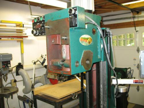
Here's a photo of my mill just before removal and dissassembly of the head.

In order to remove the head on my mill I have to run it all the way to top of the Z travel so I can release the tension on the gas springs.
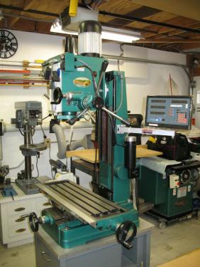
Put a piece of wood on the table so if the quill does drop down on you it will hit the wood and not the cast iron table.
Drain the oil out before starting disassembly.
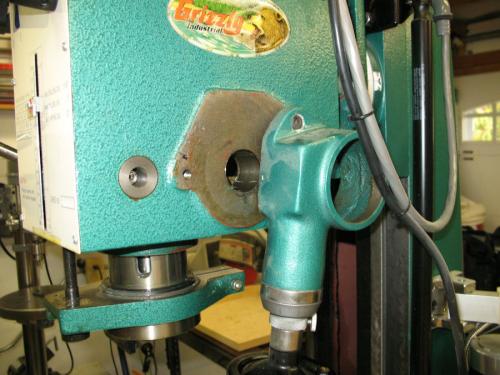
I removed the quill spring return first. Be careful while doing this because it can spin and injure you. Loosen the nut on the end but don't remove it until you release the tension. Back the housing off its notched pin and then with a firm grip slowly unwind the tension. The spring attaches to the downfeed spindle with a slot over a flat head screw. You'll have to jiggle it around to get it to release. The photo should help.
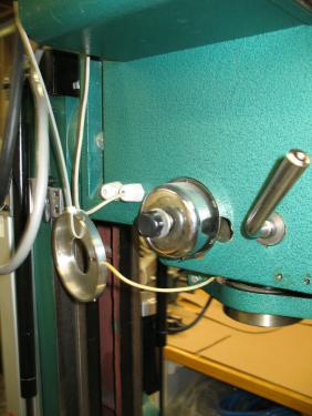
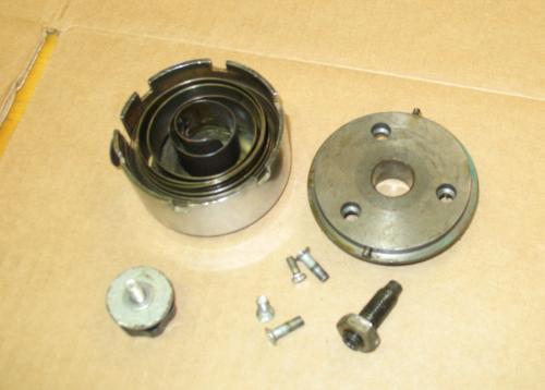
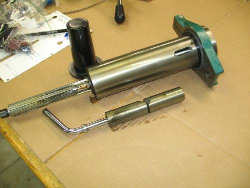
Here are the parts from the quill spring return plus the guide pin for the quill housing which must also be removed. The plate has 3 screws holding it to the head.
IMPORTANT: Lock your quill before going to the next step because it can fall out when you remove the down feed mechanism which is the only thing holding it in place.
You should be able to witdraw the downfeed handle and its spindle. Make sure your quill is locked before your remove the downfeed.
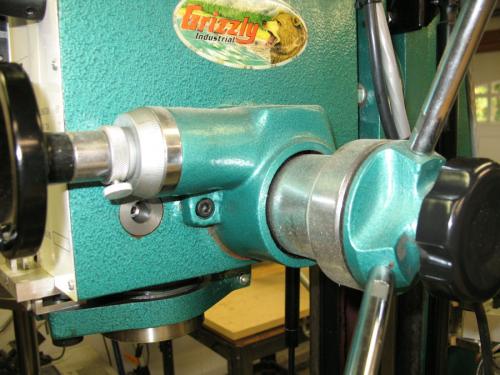
Now you can remove the fine Z axis assembly. There are two bolts holding it in place.
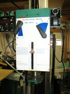
Remove the speed selector knobs and the depth gauge pointer
Remove the front panel's six screws.
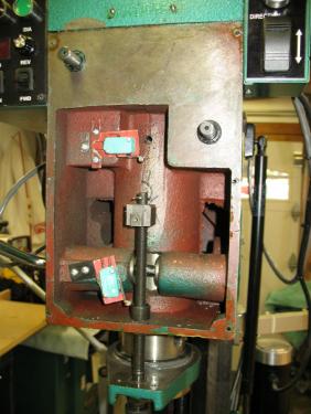
I was incorrect about the quill falling out. It can't fall out until you remove the the depth stop mechanism shown in the above photo. This is removed by releasing the cotter pin, pulling the stop block and then unscrewing the barrel on the bottom of the head.
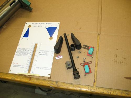
Here's the parts that were removed with the front panel including the depth limit, switches which are no longer used on my mill, the front panel, and the gear selectors.
Next I need to remove the two control boxes. These boxes vary quite bit between RF-45 versions. On mine the left box controls speed, direction, and the tachometer. The right box controls the Z axis power feed.
After the depth limit is removed, you can release the quill and gently remove it from the housing. Shown are the quill, the clamp, and the spindle cover. I'll show disassembly of the quill later.
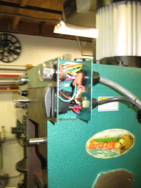
Both of my control boxes have screws from the inside that attach them to the mill head. I removed the covers and released the internal mounting screws. These boxes are usually wired to the base of the mill so they can be pushed aside freeing the head for removal.

Removing the motor before removing the head will make it that much lighter. Open the junction box and make a note of the wiring before disconnecting the wires. On my mill, there are four bolts holding the motor in place. After I removed them the motor pulls straight up. Be sure to save the key which will either be on the motor shaft or inside the hole the motor shaft fits into.
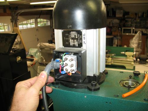
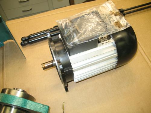
Here's my motor on the bench. I ziplock bagged parts, bolts and screws from each step so it would be easy to find things when I start putting it back together.
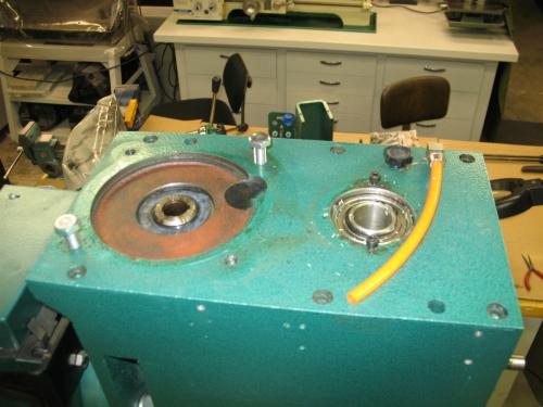
Top of the mill after the motor has been removed. The two bolts are for my lifting cable to remove the head.
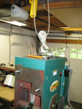
I have an overhead electric lift from Harbor Freight which is not shown in the picture. It can lift up to 800 lbs and is perfect for the head removal. It is mounted on a rail so I can slide the head over to my workbench. Once you support the head, remove the three 24 mm bolts that mount it to the yoke of the mill
Head after removal from the mill.
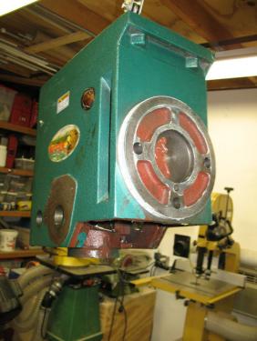
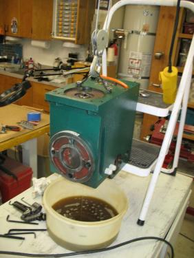
I forgot to drain the oil before removing the head so I had to do it before moving it to my workbench. I propped it up at an angle on the edge of a step stool and let it drain for a while. The drain plug on these mills is easy to miss. It's underneath the head near the third mounting bolt. The plug has got a hex allen head.
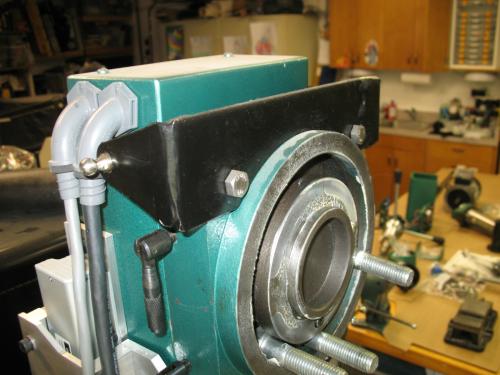
I have added a gas spring head counter balance and Z axis power feed to my mill. These are the upper gas spring mounts which I fabricated from 1/8" mild steel and two stainless ball mounts. The two electrical connections are for the motor and for the control box. The cables run through the inside of the column down through the base to the VFD.
Approximately 2 hours later I had the head on my workbench. I forgot to take picture of opening up the head but it is not as hard as I had heard it was.
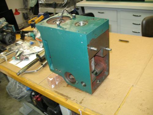
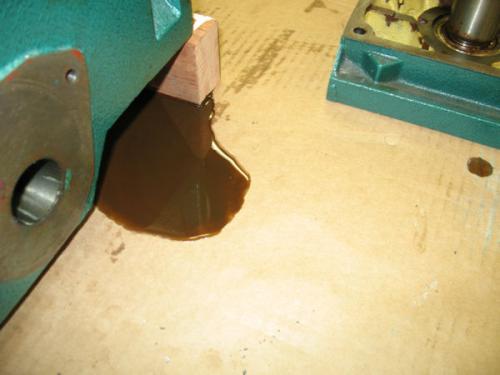
Remove the 6 bolts from the top. Lay the head on its side. At this point the oil that should have drained out already will pour on to your bench. Quickly find some rags to mop it up
Use a utility knife and a straight edge to score the joint all the way around. If you don't do this, you will get a more ragged break where the case separates.
I used a hardwood block and mallet to gently tap on the rear lip and a very narrow front lip where the front panel sits. Alternate from the back to the front and gradually the case will come apart. I did not use any prying tools between the case halves so that I would not mar the faces. My running gear came out with the top.
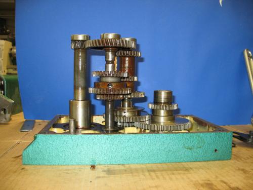
Here's the interior of my head. The brown stuff looks like rust but it is not rust. I'm not sure what it is but it looks and feels like a polishing compound which makes no sense. This contamination is reason enough to replace all bearings. There was a brown sludge in the bottom of my gearbox.

Tomorrow I'll continue with the tear down of the gearbox.
Here's the top of my head with the gear train still in place.

I removed the shaft that the motor drives using a socket of the same size as the shaft. A light tap with a rubber mallet was all it took
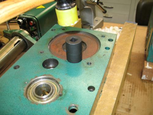
I removed each of the gear shaft end bearings with this gear puller/separator. There are 5 of these smaller bearings.
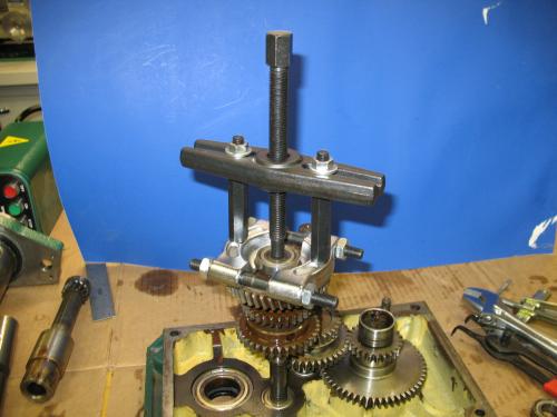
Two of the gear shafts have a plastic plug cover the end of the shaft. I used Ed's idea of drilling a small hole and inserting a screw to use as a pull to remove these plugs (not shown). After the plugs are out you need to remove the circlips on each of the holes (again not shown). The circlips are laying under the head in this photo.
I used Ed's technique of suspending the head lid over two pieces of wood and then using a socket of the correct size to tap out the gear shafts with bearings. The shafts came out with light taps of a rubber mallet.

Here's the head lid with the shafts removed.

Here are my gear shafts. The brown on the gears is not rust. It some kind of slimy residue which I have not been able to identify.
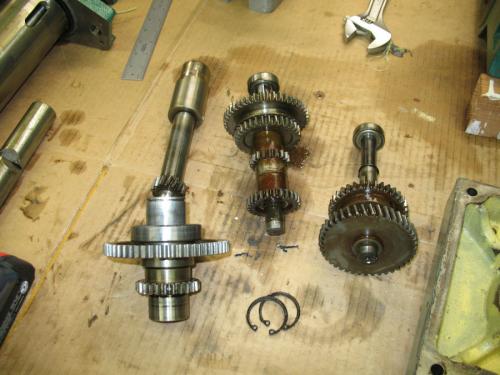
I removed the rest of the smaller bearings from each of the gear shafts using a Harbor Freight puller.
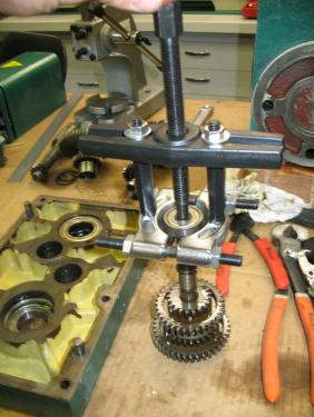
This is the Harbor Freight Gear Puller #93980 which I used.

I removed the large bearing on the end of the quill gear shaft using the gear puller. Notice the large washers Iused for backing plates to push against.

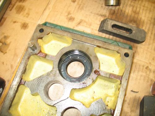
This photo shows the seal for the motor drive shaft. The spring was broken. I decided to make a tool to push this seal out and later install a new one.
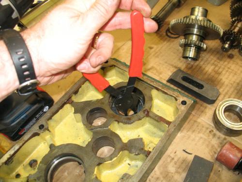
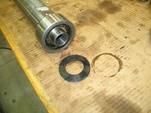
First remove the large circlip
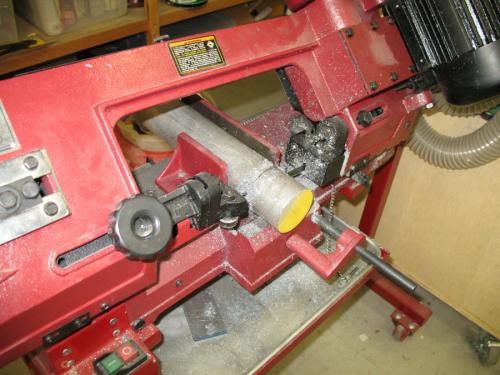
Cutting off a nice chunk of 2.5" round aluminum. Length is not important but make it long enough to reach and push the seal.
1 hour of lathe work. I made a 2 sided tool for the seal on the motor and seals on the quill gear shaft.

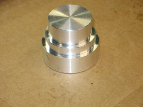
The finished tool. This tool assures that the seals will not be damaged when pressing them into place. The small end is for the quill gear shaft seals and the large end is for the motor gear shaft seal.
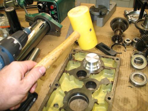
Using the tool to remove the motor gear shaft seal.
Tomorrow: Dis-assembly of the quill and tapered bearings.
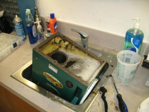
I don't have a clean tank so I used my shop sink with Dawn soap. I dried it off well to avoid any rust.
Here's a closeup of the brown muck that was inside my mill head. Obviously I cleaned all of this out.

I painted the interior with an industrial oil base paint. The proper paint is called Glyptal but it costs $50/quart. I think this paint will do the job. Paint is an optional step that is supposed to keep oil from seeping. I doubt any oil was actually seeping out. The leak I had was all through the quill.

Here's the R8 end of the quill assembly. The spindle is supported by two tapered roller bearings. My quill would not come apart with tapping of a rubber mallet so I had press the spindle out of the top tapered bearing.
The whole quill is supported by two metal plates with a hole between them. You need to catch the spindle because it can pop out suddenly. Once the top bearing has been removed, the bottom bearing can be removed by supporting the bearing on the plates and then pressing the spindle through. Again be careful to lay a pad for the spindle to fall on or keep your hand on it so it doesn't hit the floor.
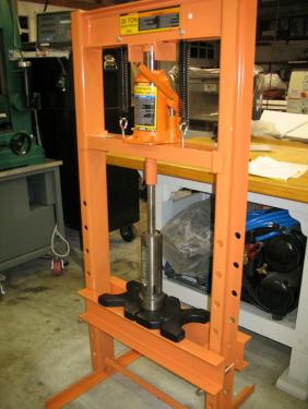
Here's the spindle removed from the quill.
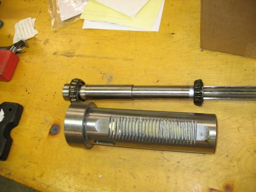
This photo shows the outer part of the bearing which must be removed and replaced with the new one.
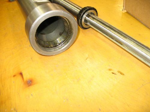
I used a bearing puller to remove the upper and lower bearing outer parts. My bearing puller is an inexpensive Harbor Freight unit. The fingers are not sharp enough to catch a thin lip so I sharpened the on a grinder.

This photo shows the R8 lower end of the quill before installation of the new bearing outer race. Make sure the bearing location is very clean. Any debris will keep the bearing from properly seating.
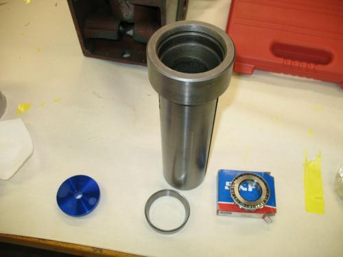
I was able to tap the outer races in with a rubber mallet and a bearing driver plate. I installed both upper and lower outer bearing races with a rubber mallet and bearing plate.
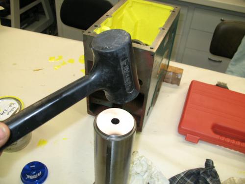
Upper installed.
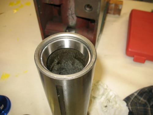
Lower inner race ready to be pressed into place.

To install the lower inner race I slid it on to the quill and then used the shop press to push it into place.
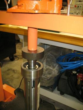
This is my first work with a shop press. If you think that I'm using the wrong technique, please post your suggestions so that others don't follow my mistake. It is important to consider how you press against bearing because they can be damaged if you do it wrong. Hopefully what I'm showing is correct.
After pressing the lower bearing race in place shown in previous section.

I greased my bearing on the spindle by hand with latex gloves. I thought this would be easier that trying to press a greased bearing into place. I also reinstalled the pin that guides R8 holders. On my mill there is a second one nearer the end that does not poke out. Maybe a spare?
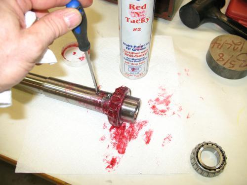
I returned the spindle to the quill and dropped the new upper bearing race onto the spindle. I used the old bearing race as a backer for pressing the new one in place.
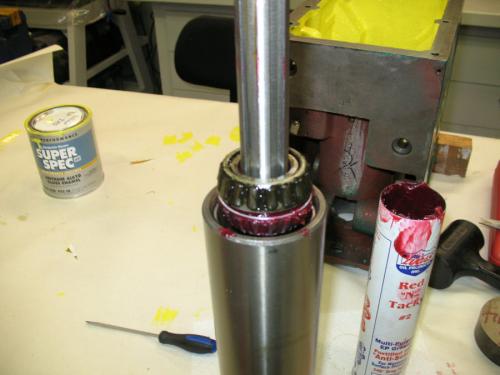
I placed the quill assembly upside down in the shop press resting on the old bearing as a backer and then pressed it into place. Gently, the bearing should not be very tight because preload should be adjusted on this bearing.
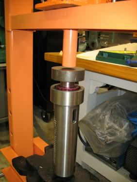
Upper bearing in place.
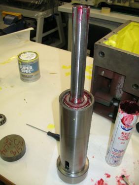
Install keeper plate and castellated nut. Tighten and back off about 1/8 turn. Set the keeper tab into the nut slot.
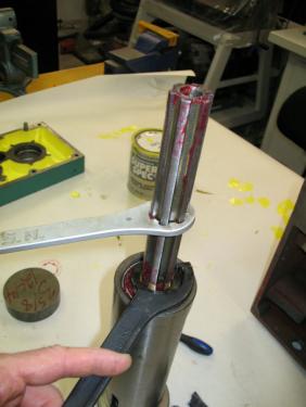
Completed quill assembly. Re-install the bottom threaded cover.

The quill assembly is now complete. Next time I'll begin reassembly of the head. There will be a couple day delay as my paint drys.
This post shows installation of the spindle drive shaft seals. The seals are pressed into a round plate that is mounted inside the head.
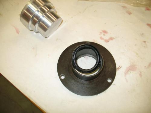
The first photo shows the a seal laying on top of the plate it will be installed in. There are 2 identical seals. They are both installed with the lips facing up and the solid side facing down. The first seal is pressed all the way down inside the plate using a tool I made to avoid damaging the seal.
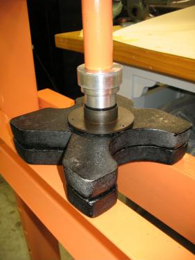
I used the shop press to install the seal. I could have installed it using a rubber mallet and the special tool.
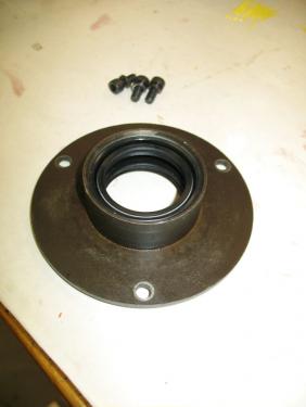
This is the first seal installed.

This is the second seal installed. The second seal sits about 1/8" bellow the top of the plate. There is a about a 1/4" gap between the 2 seals. I'll show the installation of the seal plate later.
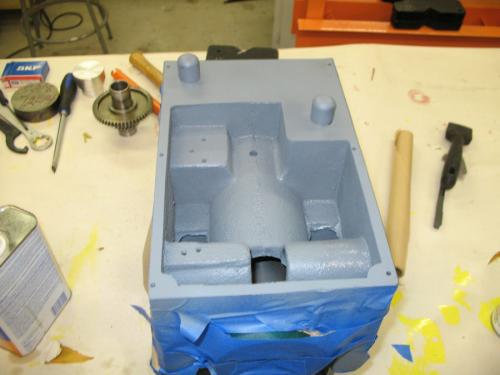
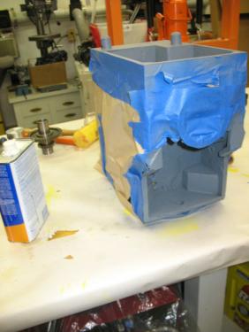
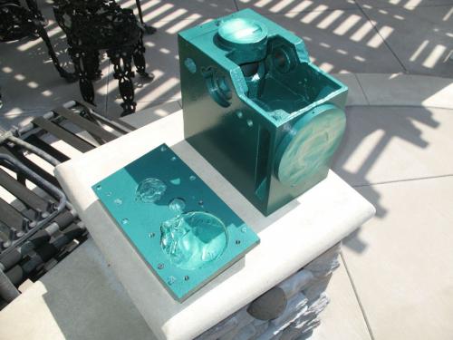
My mill head was only partially painted. Under the head where the drain plug is and behind the front panel were not painted. I primed these areas and painted them with Rustoleum Hammered Green. This color is a surprisingly good match for Grizzly Green. It even matches the textured look.
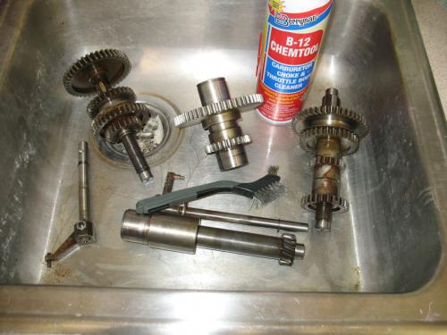
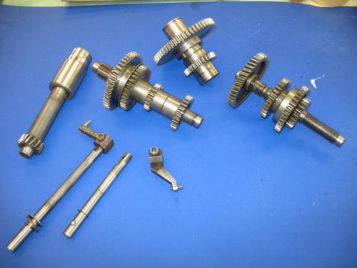
The brown sludge that was inside my gearbox left deposits on my gear shafts. I clean them up with engine cleaner and a stainless steel brush.
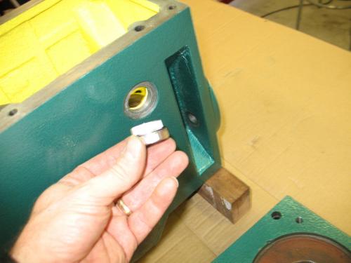
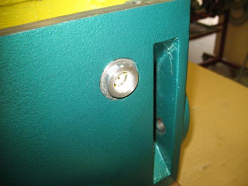
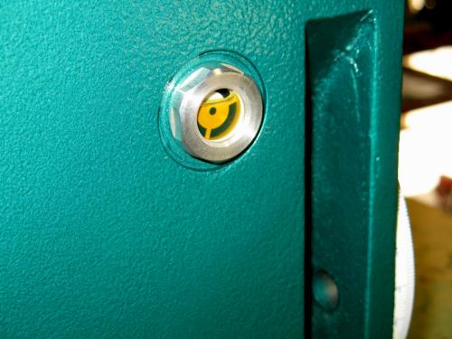
This is the sight glass which Ed found after market. It is much nicer than the original plastic sight glass. It is made from glass and aluminum and has a rubber gasket. To make sure I don't have any leaks I also used white Teflon plumber's tape on the threads.
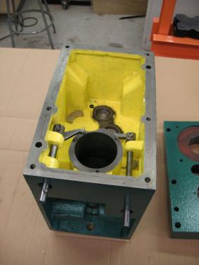
I'm now ready to start installing the gears and other hardware inside the head. The speed selector rods should be installed first because it's hard to install them after the gear shafts are installed. Remove the speed selector forks and then slide them in from the front. They are stopped by a circlip which I never removed. The seals go in after the rods are installed. Do not install the seals first because the seals hide the circlip and it's impossible to install the circlip if you install the seals first. Loosely install the selector arms. Later we will adjust them and tighten them up.
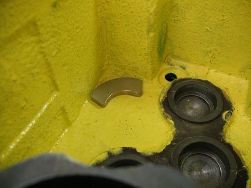
I had two powerful magnets. I put them in two of the corners of the bottom of the head. Some people prefer a magnetic dipstick or drain plug. This is what I already have. It should keep metal particles away form my bearings and gears.
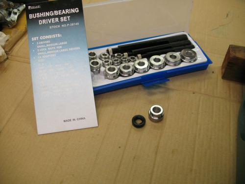
Ed made a tool to drive the selector shaft seals. I happened to have this bearing/seal driver set which came from Harbor Freight. Either way, you'll need a tool to push the seals in without damaging them. The tool needs to be a little smaller than the diameter of the seal and have a clearance hole for the shaft.
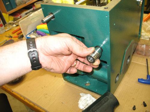
I used a driver with the correct diameter and then used another driver to extend beyond the length of the shaft. Tap the seals in with a rubber mallet. Many light taps are better than big blows for this job.
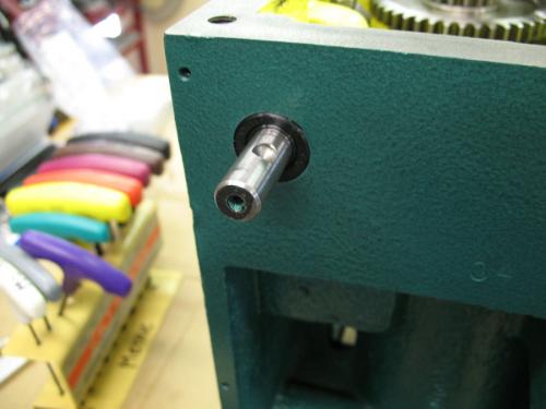
The seals should be flush with the surrounding metal. The front panel covers this area.
I'm now ready to install my gear shafts. I read a few posts and people have approached this different ways. Some have reinstalled the shafts in the gearbox lid which is the way it tends to come apart on some of these mills. The problem with this way of re-assembly is that it is very difficult to line up the gear selector arms and shoes. I decided to install my shafts into the bottom of the gearbox. I also decided to install the 5 smaller bearings that are on the ends of the shafts first.
It's probably confusing to know which gear shafts I'm referring to so here's a photo with the names I'll be using.
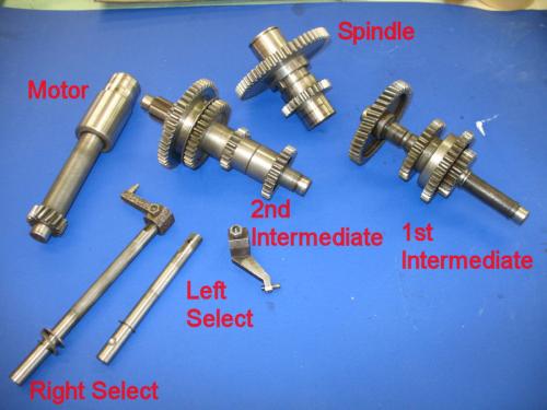
This is the 2nd Intermediate Shaft bearing installation both ends
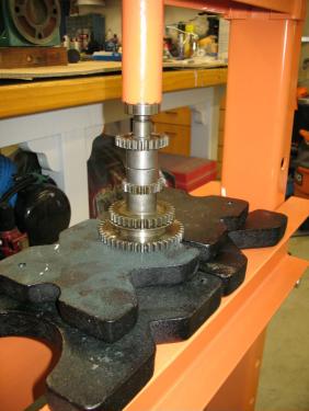
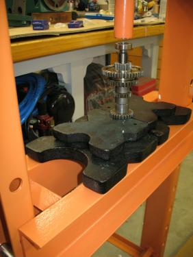
This is the 1st Intermediate Shaft Bearing installation

I also installed a small bearing on the end of the Motor Shaft. No photo. You'll notice that I haven't been mentioning bearing sizes. That is because they vary from mill to mill. Mine are not the same as Ed's. You need to disassemble your mill to find out what you have.
My plan is to install the motor, 1st, and 2nd shafts into the gearbox and then press the lid onto the top bearings. The lid must have the spindle shaft because there is no support in the bottom half of the gearbox other than the seals. I found that the machining of both the lid and the bottom allows for a somewhat looser fit on the outside diameter of the bearings so that they slide into position with out much pressure.
This post will show the installation of the gear shafts and speed selector forks. As stated earlier, I decided to do my shaft installation in the bottom of the head. Some people have done the assembly on the top half. Either way results in some bearings being pressed into place by screwing the lid down.
The shafts drop in easily on my mill. The bottom bearing hole receives the shaft bearings with just a little pressure. Install the motor shaft first and then the 1st Intermediate shaft. They need to go in this order because the gears overlap the bearing on the previous shaft. While installing the 1st Intermediate shaft, line up the right selector fork and shoe. Look at the photos if you're not sure where the shoe rides.
I already installed my speed selector rods and loosely attached the forks that carry the selector shoes. My shoes had burrs around the holes so I used a countersink to remove the burr.
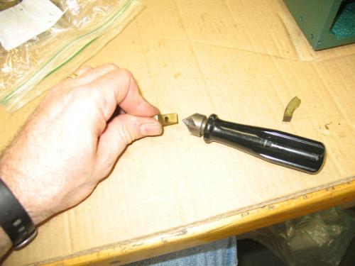
Although the gearbox will be bathed in oil, I thought it wouldn't hurt to put a little white grease on the shoe before installation.
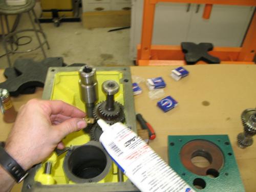
Here's the right shoe installed.

Install the 2nd Intermediate Shaft while lining up the left hand selector fork and shoe.
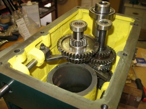
This photo shows all three shafts that will be installed in the bottom half of the head. The selector forks need to be adjusted. I noted when I was disassembling the head that the forks were not screwed onto the shafts tight. There was a small amount of compliance determined by the set screw and retainer nut. During reassembly, I tightened the set screw all the way and then backed it off about a 1/4 turn and then tightened the nut. I'm not sure why the compliance is needed but it seems like the forks were designed to be slightly loose so I put them back they way I found them.
You may recall that I said earlier that the spindle shaft must be mounted in the top half of the head. There are no bearings for this shaft in the bottom half. I'll show the installation of the spindle shaft in a later post. In this photo you'll notice that the top bearing on the 2nd Intermediate shaft is installed. I had to remove this bearing and install it in the top half because it conflicted with a large gear on the spindle shaft.
In this post I'll show installation of the quill seal plate. Earlier I showed installation of the seals in this plate.
Originally the plate had just a gasket but since I am suspicious that a leak past this plate may have occurred, I use Permatex #2 on both the mounting surface and the plate. During installation the gasket squeezed out of place which is not good. I may have assembled it too soon. I'm not recommending this but I decided to leave the gasket out and to just use the Permatex. My mounting surface has a very thin edge near the 2nd Intermediate Shaft and I feel that the gasket could not be relied on to stay on that thin surface.
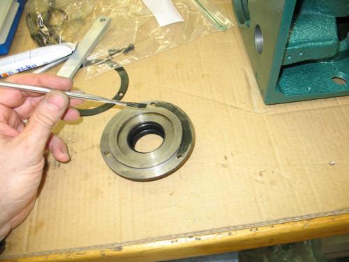
Throughout the reassembly I have replaced questionable hardware. These are new quality screws that I'm using to install the seal plate.
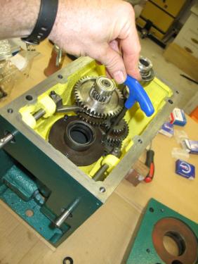
I decided to grease the seals concentrating on getting some grease between the two seals. My reasoning is that if the first seal does its job, no oil will reach the second seal and it will be running dry. I may be totally wrong on this.

Install the 3 circlips in the lid. There is one large one for the motor shaft bearing and two smaller ones for the intermediate shafts. I did not remove the circlip that was in the spindle shaft bore. You can see in the photo that its in place. The spindle shaft bor also has a spacer which I did not remove.
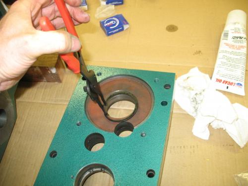
In this post I'll install the the Spindle Shaft in the top part of the head.
I already pressed one of the two bearings for the Spindle shaft onto the shaft. I could have used the press to push it into place but found that it went into place with light tapping of a rubber mallet. It rests against the circlip inside the bore. The second bearing is installed from the top.

Here's a photo from the top before installing the second bearing.
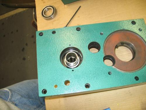
I had to modify the tool I made earlier to clear the top of the spindle shaft. The bearing rests below the top of the mill head and shaft. The bore in the tool provides the needed clearance.

Using the tool I pressed in the top bearing. This could have been done with the mallet but its easier to keep things straight using the press.

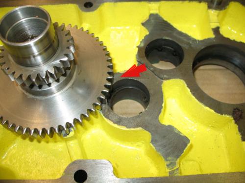
After I got the Spindle Shaft installed I realized I had a problem. This photo shows that the location for the top bearing of the 2nd Intermediate shaft conflicts with the gear on the spindle shaft. I took the spindle shaft out, moved the 2nd Intermediate shaft top bearing to the the lid and reinstalled the Spindle shaft.
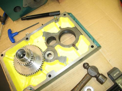
Insert the circlip on the top of the Spindle Shaft.
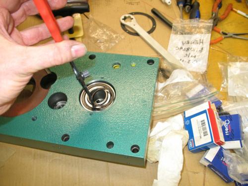
All of the gear shafts are now installed.
In this post I'll show the reassembly of the top and bottom halves of the head.
Make sure everything is correct because it will be difficult to go back from here. I used Laquer Thinner to clean the two mating surfaces. This will remove any oil, grease or paint so that the Permatex can seal properly.
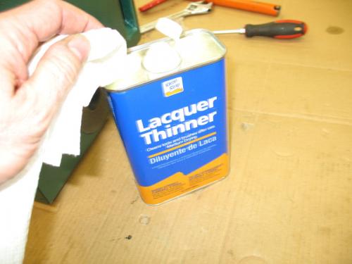
I used white grease on the top bearings to make them slide into the lid easier. Then I added the Permatex, said a prayer that it would go together easy and carefully aligned the lid pins with the bottom.
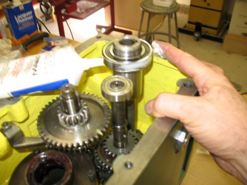
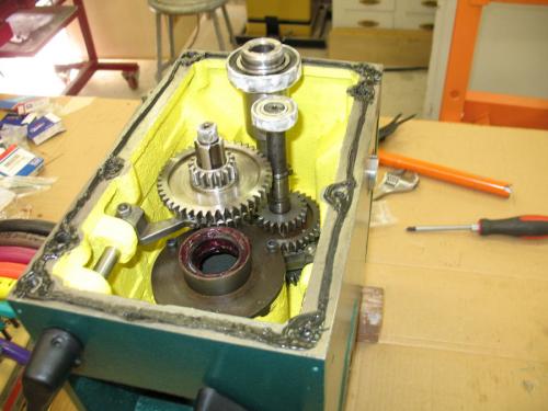
Once I got it started, I kept tapping with a rubber mallet. Many light blows are better than heavy blows. Also turn the motor shaft to make sure the gears are meshing otherwise the lid may hang up on gears that dont mesh.

Once the lid was down enough for the bolts to reach, I started tightening the bolts evenly.
Keep checking that your gap between the top and bottom is even.
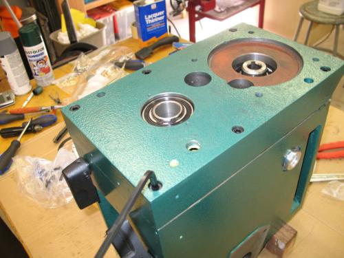
Gradually with light blows and even tightening the lid came all the way down. I kept checking that turning the motor shaft resulted in motion at the spindle shaft. I also tested the speed selectors a few times to make sure they worked.
The lid went all the way down and I had a nice small amount of squeeze out all the way around.

Whew!! Its together and turning the motor shaft results in the spindle shaft turning in all six gears.
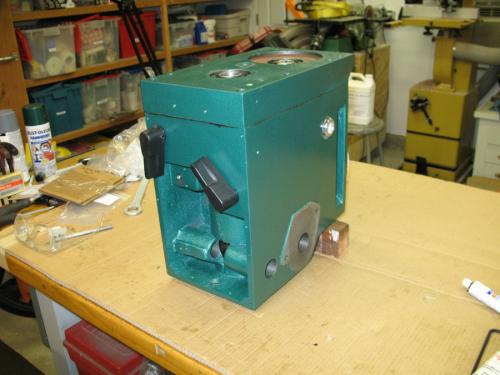
In this post and the next one, I'll reinstall various plugs, seals and vents. I'm now on the home stretch.
Reinstall the plastic plugs that cover the Intermediate bearing shafts. You may recall we removed these by drilling a small hole and inserting a sheet metal screw to pull them out.
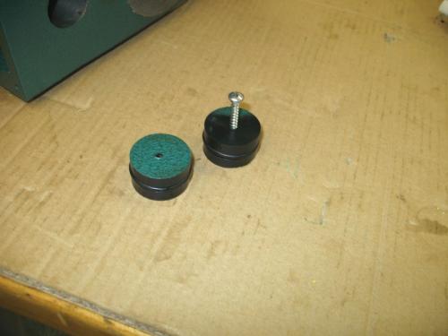
I used some white grease to make them slide in easier. I had to work the o-ring to get it to slide into the bore.

Installing the plugs.
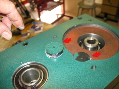
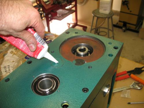
I plugged the screw holes with paint-able caulk.
I next installed the motor seal with the tool I made.
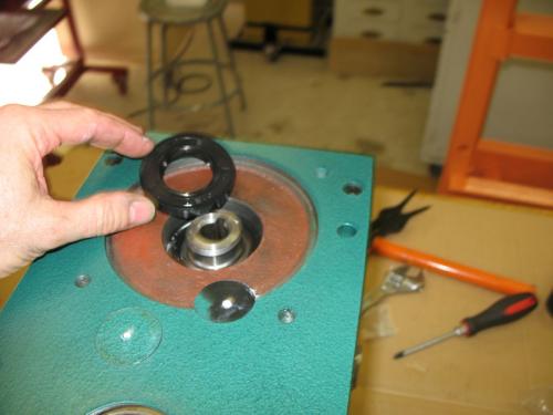
Carefully tap it in place while keeping level.

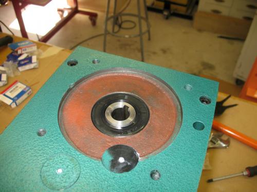
Motor seal installation complete.
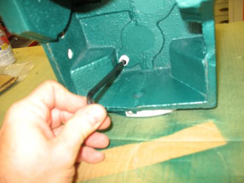
Reinstall the oil plug. I used some Teflon tape to make sure it doesn't leak.
Install the oil fill plug, the oil vent, and the spindle cover screws.
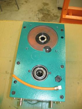
Ready to mount back on the column! I have some work to do on the mill before I reinstall the head. I'll keep you posted.
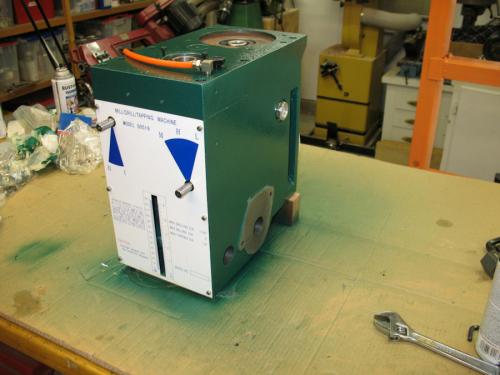
Mounting the head back on the mill.
I thought it would be a good idea to fill the head with oil and see if there were any leaks before mounting it back on the mill. It takes a about 3/4 of a gallon to fill the head and I believe that I need to top it off. Plan on buying a gallon of DTE heavy medium ISO 68 oil.
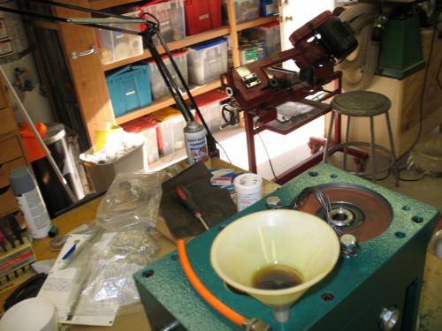
After two weeks, this is a beautiful sight and no static leaks while on the bench.
This is my setup for removing and reinstalling the head. The lift can handle up to 800 lbs. It is mounted on a heavy rail so I can lift something and then slide it over to the workbench.
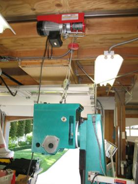
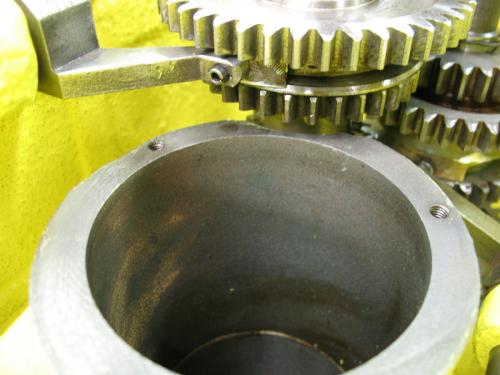
After I got the head mounted back on the mill, I realized that I could take a picture looking up into the quill cavity to see if there were any leaks. In this photo you can see my bottom seal with red grease and a thin circle of black which is the Permatex #2. I don't see any oil (YES!).

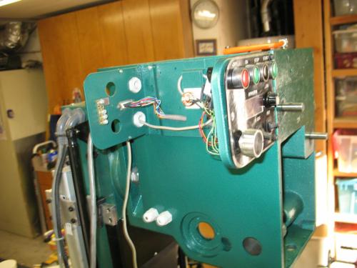
With the head mounted back on the mill column, it's time to reinstall the motor and control boxes. The control boxes on these mills vary quite a bit and mine are modified so your installation will be different. My motor is 3 phase so if you have a 1 phase motor, your connections will be different.
Reinstall my speed, direction and tachometer control box.
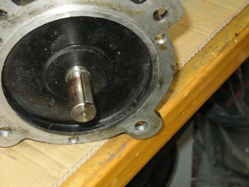
Reinsert the motor key and carefully align it with the motor shaft on the top of the head.
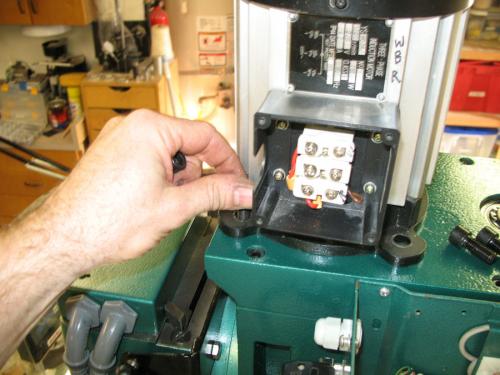
Bolt the motor down and reconnect the wires. For three phase, they need to be in the same order as they came off otherwise the motor may turn in the wrong direction.
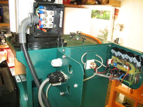
This is the control box for my Z Axis power feed.

After reinstalling my control boxes I was able to power up the mill and test the motor and gearbox. I sounds good, all speeds work, and no leaks. I am relieved.
Reinstalling the quill
Earlier I had assembled the quill but had not set the preload. The tapered bearings need to have the correct amount of tension holding the tapered inner race against the bearing surfaces. The recommended procedure is to tighten the nut all the way and then back off 1/8 of a turn. Bend up a tab on the retainer plate to hold the castellated nut in position. Some people do this adjustment again after running the machine for a while.
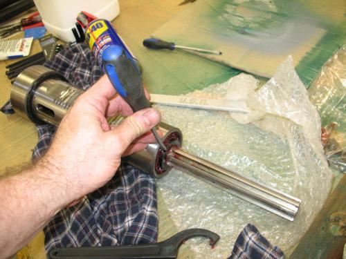
I used white grease on the quill rack gear and on the barrel. I did not like the motion of the quill with grease on the barrel so I wiped it off and used 20 wt oil instead. I'm not sure what is proper for lubrication but this should work. First reinstall your quill lock making sure the two reliefs are lined up with the quill cavity. Place some kind of soft object under you quill so if it drops, it doesn't hit your mill table. Insert the quill with a little turning motion to line up the splines with the matching spindle slots. The quill has a slot on the left side that needs to line up with a guide pin that is installed next to the return spring. Install that pin, tighten it, and then back off about a 1/4 turn, and lock the nut. Engage the down feed lock so the quill doesn't fall out.

Install the down feed shaft after lubricating the gears. I used white grease.
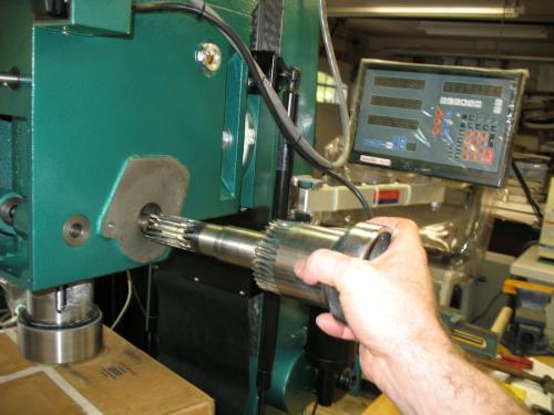
Install the key and spring for the down feed handle and slide the handle assembly on and screw on the retaining hand nut. That's the black handle used to release the fine down feed.
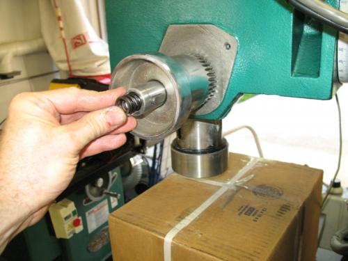
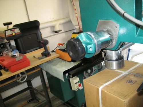
Attach the round plate that the down feed spring connects to with three screws. Install the flat head screw into the down feed shaft which clips on to the end of the down feed spring. Attaching the spring is a little tricky. You have to fiddle with the spring it until it catches. Do the next step carefully. Using gloves or a rag, turn the down feed spring counterclockwise to put tension on it. You don't have to do it in one big motion. You can do it a few half turns at a time. Each time you turn it, re-catch the down feed spring housing on the plate which has a pin to hold it. When you get the right amount of tension, the quill will return gracefully to top of it's available travel. Once the spring has the right amount of tension, replace the hand nut that holds the spring housing in place.
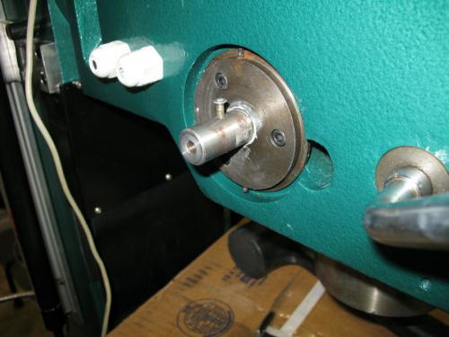
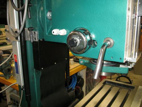
Reinstall the quill yoke and depth limit hardware and then the front panel. Reinstall the depth pointer.
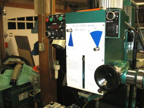
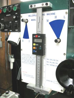
I reinstalled my down feed DRO which attaches to the front panel and has a plunger which connects to the quill yoke. Install the speed selector handles.
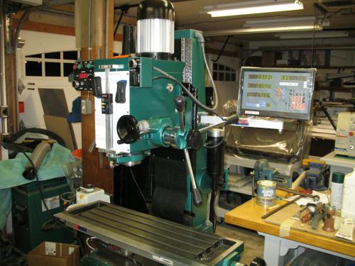
All done! I played with my "new" mill for about an hour. It runs a quieter and sounds smoother. The paint on the head is much better than before so the mill looks better.
Best of all, the next morning there was no puddle of oil on my table.
There is also a PDF can be downloaded here http://www.metalworkingfun.com/showthrea...96#pid4096
Guys,
Two days ago I started to repair my Grizzly G0519 which leaks oil from the quill. The G0519 is similar to a RF-45 Mill. My work is based on the thread by EdAK found here:
http://www.metalworkingfun.com/showthread.php?tid=157
My mill is 3 years old and started leaking small amounts of oil from the end of the quill through the bearing there. I've put up with it for about a year but was inspired by Ed's work to fix it.
Henry Arnold
Here's a photo of my mill just before removal and dissassembly of the head.
In order to remove the head on my mill I have to run it all the way to top of the Z travel so I can release the tension on the gas springs.
Put a piece of wood on the table so if the quill does drop down on you it will hit the wood and not the cast iron table.
Drain the oil out before starting disassembly.
I removed the quill spring return first. Be careful while doing this because it can spin and injure you. Loosen the nut on the end but don't remove it until you release the tension. Back the housing off its notched pin and then with a firm grip slowly unwind the tension. The spring attaches to the downfeed spindle with a slot over a flat head screw. You'll have to jiggle it around to get it to release. The photo should help.
Here are the parts from the quill spring return plus the guide pin for the quill housing which must also be removed. The plate has 3 screws holding it to the head.
IMPORTANT: Lock your quill before going to the next step because it can fall out when you remove the down feed mechanism which is the only thing holding it in place.
You should be able to witdraw the downfeed handle and its spindle. Make sure your quill is locked before your remove the downfeed.
Now you can remove the fine Z axis assembly. There are two bolts holding it in place.
Remove the speed selector knobs and the depth gauge pointer
Remove the front panel's six screws.
I was incorrect about the quill falling out. It can't fall out until you remove the the depth stop mechanism shown in the above photo. This is removed by releasing the cotter pin, pulling the stop block and then unscrewing the barrel on the bottom of the head.
Here's the parts that were removed with the front panel including the depth limit, switches which are no longer used on my mill, the front panel, and the gear selectors.
Next I need to remove the two control boxes. These boxes vary quite bit between RF-45 versions. On mine the left box controls speed, direction, and the tachometer. The right box controls the Z axis power feed.
After the depth limit is removed, you can release the quill and gently remove it from the housing. Shown are the quill, the clamp, and the spindle cover. I'll show disassembly of the quill later.
Both of my control boxes have screws from the inside that attach them to the mill head. I removed the covers and released the internal mounting screws. These boxes are usually wired to the base of the mill so they can be pushed aside freeing the head for removal.
Removing the motor before removing the head will make it that much lighter. Open the junction box and make a note of the wiring before disconnecting the wires. On my mill, there are four bolts holding the motor in place. After I removed them the motor pulls straight up. Be sure to save the key which will either be on the motor shaft or inside the hole the motor shaft fits into.
Here's my motor on the bench. I ziplock bagged parts, bolts and screws from each step so it would be easy to find things when I start putting it back together.
Top of the mill after the motor has been removed. The two bolts are for my lifting cable to remove the head.
I have an overhead electric lift from Harbor Freight which is not shown in the picture. It can lift up to 800 lbs and is perfect for the head removal. It is mounted on a rail so I can slide the head over to my workbench. Once you support the head, remove the three 24 mm bolts that mount it to the yoke of the mill
Head after removal from the mill.
I forgot to drain the oil before removing the head so I had to do it before moving it to my workbench. I propped it up at an angle on the edge of a step stool and let it drain for a while. The drain plug on these mills is easy to miss. It's underneath the head near the third mounting bolt. The plug has got a hex allen head.
I have added a gas spring head counter balance and Z axis power feed to my mill. These are the upper gas spring mounts which I fabricated from 1/8" mild steel and two stainless ball mounts. The two electrical connections are for the motor and for the control box. The cables run through the inside of the column down through the base to the VFD.
Approximately 2 hours later I had the head on my workbench. I forgot to take picture of opening up the head but it is not as hard as I had heard it was.
Remove the 6 bolts from the top. Lay the head on its side. At this point the oil that should have drained out already will pour on to your bench. Quickly find some rags to mop it up

Use a utility knife and a straight edge to score the joint all the way around. If you don't do this, you will get a more ragged break where the case separates.
I used a hardwood block and mallet to gently tap on the rear lip and a very narrow front lip where the front panel sits. Alternate from the back to the front and gradually the case will come apart. I did not use any prying tools between the case halves so that I would not mar the faces. My running gear came out with the top.
Here's the interior of my head. The brown stuff looks like rust but it is not rust. I'm not sure what it is but it looks and feels like a polishing compound which makes no sense. This contamination is reason enough to replace all bearings. There was a brown sludge in the bottom of my gearbox.
Tomorrow I'll continue with the tear down of the gearbox.
Here's the top of my head with the gear train still in place.
I removed the shaft that the motor drives using a socket of the same size as the shaft. A light tap with a rubber mallet was all it took
I removed each of the gear shaft end bearings with this gear puller/separator. There are 5 of these smaller bearings.
Two of the gear shafts have a plastic plug cover the end of the shaft. I used Ed's idea of drilling a small hole and inserting a screw to use as a pull to remove these plugs (not shown). After the plugs are out you need to remove the circlips on each of the holes (again not shown). The circlips are laying under the head in this photo.
I used Ed's technique of suspending the head lid over two pieces of wood and then using a socket of the correct size to tap out the gear shafts with bearings. The shafts came out with light taps of a rubber mallet.
Here's the head lid with the shafts removed.
Here are my gear shafts. The brown on the gears is not rust. It some kind of slimy residue which I have not been able to identify.
I removed the rest of the smaller bearings from each of the gear shafts using a Harbor Freight puller.
This is the Harbor Freight Gear Puller #93980 which I used.
I removed the large bearing on the end of the quill gear shaft using the gear puller. Notice the large washers Iused for backing plates to push against.
This photo shows the seal for the motor drive shaft. The spring was broken. I decided to make a tool to push this seal out and later install a new one.
First remove the large circlip
Cutting off a nice chunk of 2.5" round aluminum. Length is not important but make it long enough to reach and push the seal.
1 hour of lathe work. I made a 2 sided tool for the seal on the motor and seals on the quill gear shaft.
The finished tool. This tool assures that the seals will not be damaged when pressing them into place. The small end is for the quill gear shaft seals and the large end is for the motor gear shaft seal.
Using the tool to remove the motor gear shaft seal.
Tomorrow: Dis-assembly of the quill and tapered bearings.
I don't have a clean tank so I used my shop sink with Dawn soap. I dried it off well to avoid any rust.
Here's a closeup of the brown muck that was inside my mill head. Obviously I cleaned all of this out.
I painted the interior with an industrial oil base paint. The proper paint is called Glyptal but it costs $50/quart. I think this paint will do the job. Paint is an optional step that is supposed to keep oil from seeping. I doubt any oil was actually seeping out. The leak I had was all through the quill.
Here's the R8 end of the quill assembly. The spindle is supported by two tapered roller bearings. My quill would not come apart with tapping of a rubber mallet so I had press the spindle out of the top tapered bearing.
The whole quill is supported by two metal plates with a hole between them. You need to catch the spindle because it can pop out suddenly. Once the top bearing has been removed, the bottom bearing can be removed by supporting the bearing on the plates and then pressing the spindle through. Again be careful to lay a pad for the spindle to fall on or keep your hand on it so it doesn't hit the floor.
Here's the spindle removed from the quill.
This photo shows the outer part of the bearing which must be removed and replaced with the new one.
I used a bearing puller to remove the upper and lower bearing outer parts. My bearing puller is an inexpensive Harbor Freight unit. The fingers are not sharp enough to catch a thin lip so I sharpened the on a grinder.
This photo shows the R8 lower end of the quill before installation of the new bearing outer race. Make sure the bearing location is very clean. Any debris will keep the bearing from properly seating.
I was able to tap the outer races in with a rubber mallet and a bearing driver plate. I installed both upper and lower outer bearing races with a rubber mallet and bearing plate.
Upper installed.
Lower inner race ready to be pressed into place.
To install the lower inner race I slid it on to the quill and then used the shop press to push it into place.
This is my first work with a shop press. If you think that I'm using the wrong technique, please post your suggestions so that others don't follow my mistake. It is important to consider how you press against bearing because they can be damaged if you do it wrong. Hopefully what I'm showing is correct.
After pressing the lower bearing race in place shown in previous section.
I greased my bearing on the spindle by hand with latex gloves. I thought this would be easier that trying to press a greased bearing into place. I also reinstalled the pin that guides R8 holders. On my mill there is a second one nearer the end that does not poke out. Maybe a spare?
I returned the spindle to the quill and dropped the new upper bearing race onto the spindle. I used the old bearing race as a backer for pressing the new one in place.
I placed the quill assembly upside down in the shop press resting on the old bearing as a backer and then pressed it into place. Gently, the bearing should not be very tight because preload should be adjusted on this bearing.
Upper bearing in place.
Install keeper plate and castellated nut. Tighten and back off about 1/8 turn. Set the keeper tab into the nut slot.
Completed quill assembly. Re-install the bottom threaded cover.
The quill assembly is now complete. Next time I'll begin reassembly of the head. There will be a couple day delay as my paint drys.

This post shows installation of the spindle drive shaft seals. The seals are pressed into a round plate that is mounted inside the head.
The first photo shows the a seal laying on top of the plate it will be installed in. There are 2 identical seals. They are both installed with the lips facing up and the solid side facing down. The first seal is pressed all the way down inside the plate using a tool I made to avoid damaging the seal.
I used the shop press to install the seal. I could have installed it using a rubber mallet and the special tool.
This is the first seal installed.
This is the second seal installed. The second seal sits about 1/8" bellow the top of the plate. There is a about a 1/4" gap between the 2 seals. I'll show the installation of the seal plate later.
My mill head was only partially painted. Under the head where the drain plug is and behind the front panel were not painted. I primed these areas and painted them with Rustoleum Hammered Green. This color is a surprisingly good match for Grizzly Green. It even matches the textured look.
The brown sludge that was inside my gearbox left deposits on my gear shafts. I clean them up with engine cleaner and a stainless steel brush.
This is the sight glass which Ed found after market. It is much nicer than the original plastic sight glass. It is made from glass and aluminum and has a rubber gasket. To make sure I don't have any leaks I also used white Teflon plumber's tape on the threads.
I'm now ready to start installing the gears and other hardware inside the head. The speed selector rods should be installed first because it's hard to install them after the gear shafts are installed. Remove the speed selector forks and then slide them in from the front. They are stopped by a circlip which I never removed. The seals go in after the rods are installed. Do not install the seals first because the seals hide the circlip and it's impossible to install the circlip if you install the seals first. Loosely install the selector arms. Later we will adjust them and tighten them up.
I had two powerful magnets. I put them in two of the corners of the bottom of the head. Some people prefer a magnetic dipstick or drain plug. This is what I already have. It should keep metal particles away form my bearings and gears.
Ed made a tool to drive the selector shaft seals. I happened to have this bearing/seal driver set which came from Harbor Freight. Either way, you'll need a tool to push the seals in without damaging them. The tool needs to be a little smaller than the diameter of the seal and have a clearance hole for the shaft.
I used a driver with the correct diameter and then used another driver to extend beyond the length of the shaft. Tap the seals in with a rubber mallet. Many light taps are better than big blows for this job.
The seals should be flush with the surrounding metal. The front panel covers this area.
I'm now ready to install my gear shafts. I read a few posts and people have approached this different ways. Some have reinstalled the shafts in the gearbox lid which is the way it tends to come apart on some of these mills. The problem with this way of re-assembly is that it is very difficult to line up the gear selector arms and shoes. I decided to install my shafts into the bottom of the gearbox. I also decided to install the 5 smaller bearings that are on the ends of the shafts first.
It's probably confusing to know which gear shafts I'm referring to so here's a photo with the names I'll be using.
This is the 2nd Intermediate Shaft bearing installation both ends
This is the 1st Intermediate Shaft Bearing installation
I also installed a small bearing on the end of the Motor Shaft. No photo. You'll notice that I haven't been mentioning bearing sizes. That is because they vary from mill to mill. Mine are not the same as Ed's. You need to disassemble your mill to find out what you have.
My plan is to install the motor, 1st, and 2nd shafts into the gearbox and then press the lid onto the top bearings. The lid must have the spindle shaft because there is no support in the bottom half of the gearbox other than the seals. I found that the machining of both the lid and the bottom allows for a somewhat looser fit on the outside diameter of the bearings so that they slide into position with out much pressure.
This post will show the installation of the gear shafts and speed selector forks. As stated earlier, I decided to do my shaft installation in the bottom of the head. Some people have done the assembly on the top half. Either way results in some bearings being pressed into place by screwing the lid down.
The shafts drop in easily on my mill. The bottom bearing hole receives the shaft bearings with just a little pressure. Install the motor shaft first and then the 1st Intermediate shaft. They need to go in this order because the gears overlap the bearing on the previous shaft. While installing the 1st Intermediate shaft, line up the right selector fork and shoe. Look at the photos if you're not sure where the shoe rides.
I already installed my speed selector rods and loosely attached the forks that carry the selector shoes. My shoes had burrs around the holes so I used a countersink to remove the burr.
Although the gearbox will be bathed in oil, I thought it wouldn't hurt to put a little white grease on the shoe before installation.
Here's the right shoe installed.
Install the 2nd Intermediate Shaft while lining up the left hand selector fork and shoe.
This photo shows all three shafts that will be installed in the bottom half of the head. The selector forks need to be adjusted. I noted when I was disassembling the head that the forks were not screwed onto the shafts tight. There was a small amount of compliance determined by the set screw and retainer nut. During reassembly, I tightened the set screw all the way and then backed it off about a 1/4 turn and then tightened the nut. I'm not sure why the compliance is needed but it seems like the forks were designed to be slightly loose so I put them back they way I found them.
You may recall that I said earlier that the spindle shaft must be mounted in the top half of the head. There are no bearings for this shaft in the bottom half. I'll show the installation of the spindle shaft in a later post. In this photo you'll notice that the top bearing on the 2nd Intermediate shaft is installed. I had to remove this bearing and install it in the top half because it conflicted with a large gear on the spindle shaft.
In this post I'll show installation of the quill seal plate. Earlier I showed installation of the seals in this plate.
Originally the plate had just a gasket but since I am suspicious that a leak past this plate may have occurred, I use Permatex #2 on both the mounting surface and the plate. During installation the gasket squeezed out of place which is not good. I may have assembled it too soon. I'm not recommending this but I decided to leave the gasket out and to just use the Permatex. My mounting surface has a very thin edge near the 2nd Intermediate Shaft and I feel that the gasket could not be relied on to stay on that thin surface.
Throughout the reassembly I have replaced questionable hardware. These are new quality screws that I'm using to install the seal plate.
I decided to grease the seals concentrating on getting some grease between the two seals. My reasoning is that if the first seal does its job, no oil will reach the second seal and it will be running dry. I may be totally wrong on this.
Install the 3 circlips in the lid. There is one large one for the motor shaft bearing and two smaller ones for the intermediate shafts. I did not remove the circlip that was in the spindle shaft bore. You can see in the photo that its in place. The spindle shaft bor also has a spacer which I did not remove.
In this post I'll install the the Spindle Shaft in the top part of the head.
I already pressed one of the two bearings for the Spindle shaft onto the shaft. I could have used the press to push it into place but found that it went into place with light tapping of a rubber mallet. It rests against the circlip inside the bore. The second bearing is installed from the top.
Here's a photo from the top before installing the second bearing.
I had to modify the tool I made earlier to clear the top of the spindle shaft. The bearing rests below the top of the mill head and shaft. The bore in the tool provides the needed clearance.
Using the tool I pressed in the top bearing. This could have been done with the mallet but its easier to keep things straight using the press.
After I got the Spindle Shaft installed I realized I had a problem. This photo shows that the location for the top bearing of the 2nd Intermediate shaft conflicts with the gear on the spindle shaft. I took the spindle shaft out, moved the 2nd Intermediate shaft top bearing to the the lid and reinstalled the Spindle shaft.
Insert the circlip on the top of the Spindle Shaft.
All of the gear shafts are now installed.
In this post I'll show the reassembly of the top and bottom halves of the head.
Make sure everything is correct because it will be difficult to go back from here. I used Laquer Thinner to clean the two mating surfaces. This will remove any oil, grease or paint so that the Permatex can seal properly.
I used white grease on the top bearings to make them slide into the lid easier. Then I added the Permatex, said a prayer that it would go together easy and carefully aligned the lid pins with the bottom.
Once I got it started, I kept tapping with a rubber mallet. Many light blows are better than heavy blows. Also turn the motor shaft to make sure the gears are meshing otherwise the lid may hang up on gears that dont mesh.
Once the lid was down enough for the bolts to reach, I started tightening the bolts evenly.
Keep checking that your gap between the top and bottom is even.
Gradually with light blows and even tightening the lid came all the way down. I kept checking that turning the motor shaft resulted in motion at the spindle shaft. I also tested the speed selectors a few times to make sure they worked.
The lid went all the way down and I had a nice small amount of squeeze out all the way around.
Whew!! Its together and turning the motor shaft results in the spindle shaft turning in all six gears.
In this post and the next one, I'll reinstall various plugs, seals and vents. I'm now on the home stretch.
Reinstall the plastic plugs that cover the Intermediate bearing shafts. You may recall we removed these by drilling a small hole and inserting a sheet metal screw to pull them out.
I used some white grease to make them slide in easier. I had to work the o-ring to get it to slide into the bore.
Installing the plugs.
I plugged the screw holes with paint-able caulk.
I next installed the motor seal with the tool I made.
Carefully tap it in place while keeping level.
Motor seal installation complete.
Reinstall the oil plug. I used some Teflon tape to make sure it doesn't leak.
Install the oil fill plug, the oil vent, and the spindle cover screws.
Ready to mount back on the column! I have some work to do on the mill before I reinstall the head. I'll keep you posted.
Mounting the head back on the mill.
I thought it would be a good idea to fill the head with oil and see if there were any leaks before mounting it back on the mill. It takes a about 3/4 of a gallon to fill the head and I believe that I need to top it off. Plan on buying a gallon of DTE heavy medium ISO 68 oil.
After two weeks, this is a beautiful sight and no static leaks while on the bench.
This is my setup for removing and reinstalling the head. The lift can handle up to 800 lbs. It is mounted on a heavy rail so I can lift something and then slide it over to the workbench.
After I got the head mounted back on the mill, I realized that I could take a picture looking up into the quill cavity to see if there were any leaks. In this photo you can see my bottom seal with red grease and a thin circle of black which is the Permatex #2. I don't see any oil (YES!).
With the head mounted back on the mill column, it's time to reinstall the motor and control boxes. The control boxes on these mills vary quite a bit and mine are modified so your installation will be different. My motor is 3 phase so if you have a 1 phase motor, your connections will be different.
Reinstall my speed, direction and tachometer control box.
Reinsert the motor key and carefully align it with the motor shaft on the top of the head.
Bolt the motor down and reconnect the wires. For three phase, they need to be in the same order as they came off otherwise the motor may turn in the wrong direction.
This is the control box for my Z Axis power feed.
After reinstalling my control boxes I was able to power up the mill and test the motor and gearbox. I sounds good, all speeds work, and no leaks. I am relieved.
Reinstalling the quill
Earlier I had assembled the quill but had not set the preload. The tapered bearings need to have the correct amount of tension holding the tapered inner race against the bearing surfaces. The recommended procedure is to tighten the nut all the way and then back off 1/8 of a turn. Bend up a tab on the retainer plate to hold the castellated nut in position. Some people do this adjustment again after running the machine for a while.
I used white grease on the quill rack gear and on the barrel. I did not like the motion of the quill with grease on the barrel so I wiped it off and used 20 wt oil instead. I'm not sure what is proper for lubrication but this should work. First reinstall your quill lock making sure the two reliefs are lined up with the quill cavity. Place some kind of soft object under you quill so if it drops, it doesn't hit your mill table. Insert the quill with a little turning motion to line up the splines with the matching spindle slots. The quill has a slot on the left side that needs to line up with a guide pin that is installed next to the return spring. Install that pin, tighten it, and then back off about a 1/4 turn, and lock the nut. Engage the down feed lock so the quill doesn't fall out.
Install the down feed shaft after lubricating the gears. I used white grease.
Install the key and spring for the down feed handle and slide the handle assembly on and screw on the retaining hand nut. That's the black handle used to release the fine down feed.
Attach the round plate that the down feed spring connects to with three screws. Install the flat head screw into the down feed shaft which clips on to the end of the down feed spring. Attaching the spring is a little tricky. You have to fiddle with the spring it until it catches. Do the next step carefully. Using gloves or a rag, turn the down feed spring counterclockwise to put tension on it. You don't have to do it in one big motion. You can do it a few half turns at a time. Each time you turn it, re-catch the down feed spring housing on the plate which has a pin to hold it. When you get the right amount of tension, the quill will return gracefully to top of it's available travel. Once the spring has the right amount of tension, replace the hand nut that holds the spring housing in place.
Reinstall the quill yoke and depth limit hardware and then the front panel. Reinstall the depth pointer.
I reinstalled my down feed DRO which attaches to the front panel and has a plunger which connects to the quill yoke. Install the speed selector handles.
All done! I played with my "new" mill for about an hour. It runs a quieter and sounds smoother. The paint on the head is much better than before so the mill looks better.
Best of all, the next morning there was no puddle of oil on my table.
henryarnold, proud to be a member of MetalworkingFun Forum since Apr 2012.


