10-06-2012, 12:30 PM
First thing, I want to thank Henry Arnold for his excellent how-to writeup on adding a motor to the z-axis of a RF45. I have modeled my install after his with some slight differences. My mill has the z-axis crank located on the left side which is awkward to use as I am right handed. I first added a gas spring which did make it easier to raise the head but still not what I wanted. Here it is before the mod.

I am using the same pulleys and belt as Henry and sourced them at McMaster-Carr. I found a motor and controller on e-bay and mocked them up on the bench to see if the motor worked and could be reversed.

With this working OK I had to next bore out the existing hole in the pulley to fit the crankshaft. This was the first time using the boring bar and it turned out OK.


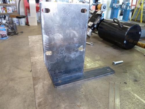
I designed the motor mount to use 2 of the 3 bolts that mount the crankshaft assembly. The 2 plates were cutout and slots milled for the motor mount bolts. This will allow the belt to be tensioned.

The plates were setup and then welded.


Here the motor is mocked up with the pulleys and belt.

I built up a breadboard circuit to test the motor function.

The first motor turned out to be too small and would not raise the head even after adding a second gas spring. Back to e-bay for a bigger motor. This one is 1/4 hp and lifts the head without a wimper. It may be overkill but it cost the same as the smaller motor and works. The next installment will outline the electrical enclosures and final installation.
I am using the same pulleys and belt as Henry and sourced them at McMaster-Carr. I found a motor and controller on e-bay and mocked them up on the bench to see if the motor worked and could be reversed.
With this working OK I had to next bore out the existing hole in the pulley to fit the crankshaft. This was the first time using the boring bar and it turned out OK.
I designed the motor mount to use 2 of the 3 bolts that mount the crankshaft assembly. The 2 plates were cutout and slots milled for the motor mount bolts. This will allow the belt to be tensioned.
The plates were setup and then welded.
Here the motor is mocked up with the pulleys and belt.
I built up a breadboard circuit to test the motor function.
The first motor turned out to be too small and would not raise the head even after adding a second gas spring. Back to e-bay for a bigger motor. This one is 1/4 hp and lifts the head without a wimper. It may be overkill but it cost the same as the smaller motor and works. The next installment will outline the electrical enclosures and final installation.
Collecting tools for 30 years.


![[Image: TomsTechLogo-Profile.png]](http://tomstechniques.com/wp-content/uploads/2013/11/TomsTechLogo-Profile.png)
