Adding power to the z-axis
#1
First thing, I want to thank Henry Arnold for his excellent how-to writeup on adding a motor to the z-axis of a RF45. I have modeled my install after his with some slight differences. My mill has the z-axis crank located on the left side which is awkward to use as I am right handed. I first added a gas spring which did make it easier to raise the head but still not what I wanted. Here it is before the mod.
   
I am using the same pulleys and belt as Henry and sourced them at McMaster-Carr. I found a motor and controller on e-bay and mocked them up on the bench to see if the motor worked and could be reversed.
   
With this working OK I had to next bore out the existing hole in the pulley to fit the crankshaft. This was the first time using the boring bar and it turned out OK.


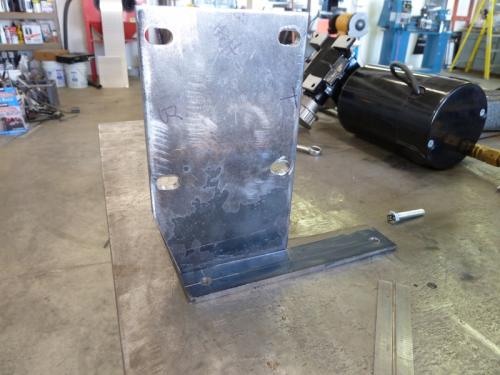
I designed the motor mount to use 2 of the 3 bolts that mount the crankshaft assembly. The 2 plates were cutout and slots milled for the motor mount bolts. This will allow the belt to be tensioned.
   
The plates were setup and then welded.


Here the motor is mocked up with the pulleys and belt.
   
I built up a breadboard circuit to test the motor function.
   
The first motor turned out to be too small and would not raise the head even after adding a second gas spring. Back to e-bay for a bigger motor. This one is 1/4 hp and lifts the head without a wimper. It may be overkill but it cost the same as the smaller motor and works. The next installment will outline the electrical enclosures and final installation.
Collecting tools for 30 years.
Reply
Thanks given by:
#2
I wanted the main electrical box to both house the motor controller and supply 110V power for the x-axis motor drive and any lights or other additions like a DRO that I might add later on. I made the box out of 18ga steel and tig welded it up. I added 4 tabs to the corners for the screws that hold the lid on and cut the holes for 2 standard outlet plugs. Here's how the layout looks.
   
   
The smaller box is two pieces shaped in a "U" and will house the up/down switch and speed control.
   
   
Off to the paint booth for a matching coat of blue.
   
Most of the wiring for the main electrical bax was done at the bench.
   
I mounted the box at the back of the mill column with the main power switch and circuit breaker up for easy access.
   
I mounted the small box next and hooked up the wires.


Here are the final installation pics showing the wire routing.


This is so nice to use and was well worth the effort.
Collecting tools for 30 years.
Reply
Thanks given by:
#3
Dan,

Very nice write-up and great pictures. Smiley-signs107

What's the RPMs of the motor you got? I need to motorize the head lift on my Enco mill also.

Thanks,
Ed
Reply
Thanks given by:
#4
(10-06-2012, 01:06 PM)EdK Wrote: Dan,

Very nice write-up and great pictures. Smiley-signs107

What's the RPMs of the motor you got? I need to motorize the head lift on my Enco mill also.

Thanks,
Ed

Ed,

The motor I used is 140 rpm. I think 200 at the top end would work great. Just make sure you have enough torque. My first motor was 1/12hp, 200 rpm but only 10 in-lbs torque and couldn't move the head even with two 100lb springs. I would guess anything over 30 in-lbs would be fine.

Dan
Collecting tools for 30 years.
Reply
Thanks given by: EdK
#5
(10-06-2012, 01:06 PM)EdK Wrote: Very nice write-up and great pictures. Smiley-signs107

Smiley-signs064

Paint booth!!!??? Jawdrop Worthy Worthy Worthy
Willie
Reply
Thanks given by:
#6
(10-06-2012, 08:45 PM)Highpower Wrote:
(10-06-2012, 01:06 PM)EdK Wrote: Very nice write-up and great pictures. Smiley-signs107

Smiley-signs064

Paint booth!!!??? Jawdrop Worthy Worthy Worthy

Yah, I built a booth into a corner of my shop. I was painting car parts in the loft above the fab area without any ventlation which wasn't a great idea so I walled in an area in the corner of the shop for painting. This also gave me a great place for storage that kept the general shop grunge off. This is a much safer setup when painting parts than what I had before.
Collecting tools for 30 years.
Reply
Thanks given by:
#7
Excellent! Is that usable for really minor up and down, as well as the long travel? I. E., for adjusting the Z by .010 or .015? I would love to mechanize the knee on my Rockwell.

Also, I'm curious about the gas lift. I can see that it makes going up easier, but doesn't it make going down, harder?
Reply
Thanks given by:
#8
Nice job Dan. It's great to see a project like this shown from concept to completion. Great pics as well.

Is there a reason why you decided to use a belt drive instead of direct drive with a flexible coupling?

It must be nice to have the room for a paint booth. Most of my stuff has to wait for a nice day to be shot in the driveway, including my cars.

Tom
[Image: TomsTechLogo-Profile.png]
Reply
Thanks given by:
#9
(10-07-2012, 09:26 AM)Wawoodman Wrote: Also, I'm curious about the gas lift. I can see that it makes going up easier, but doesn't it make going down, harder?


I put gas springs on my ZX45 same as a RF, and no it doesn't make it harder going down. the springs act like a counter weight just without all the other stuff like a weight and cables. The one problem I have is with the position that I mounted the springs at cause them to actually bind up I think ( may just be my column needing some TLC) I know that they loose lift at the top cause of the angle that they are at.

But in the middle of the travel range they work great and with the hand crank I could raise the head by using the crank and only two fingers to turn it.

need to find the pictures and post them here or go download them from the old mill site.
dallen, proud to be a member of MetalworkingFun Forum since Apr 2012.

If life seems normal, your not going fast enough! Tongue
Reply
Thanks given by:
#10
(10-07-2012, 09:26 AM)Wawoodman Wrote: Excellent! Is that usable for really minor up and down, as well as the long travel? I. E., for adjusting the Z by .010 or .015? I would love to mechanize the knee on my Rockwell.

Also, I'm curious about the gas lift. I can see that it makes going up easier, but doesn't it make going down, harder?

I checked this morning and the shortest movement at full speed was about 3/8". I need to change the speed pot as it is stuck at full speed but it might be possible for a smaller increment. I don't think you could hit .015 as the motor has some run on.

On my mill, with 2 springs the cranking force is about equal between up and down. When I only had 1 spring hooked up going up was hard and going down felt like it was freewheeling.

Dan
Collecting tools for 30 years.
Reply
Thanks given by:


Users browsing this thread: 2 Guest(s)